


14.1 Fundamental settings
14-33
Converter communication module version number
You can check a Converter communication module version number using the following
machine data for each drive. (Those drives under the same Converter show the same version
number.)
• MD1795 OPTMOD_FIRMWARE_VIRSION (For each axis)
Meaning:
Communication software version number (Read-only)
Servo drive unit version number
Connect a Digital operator to a Converter and check the version number in the following
procedures:
1. Select a drive (dr1, dr2...: the drive number is a value, 1 more than the rotary switch set-
ting value of each drive) to check by pressing [Up] or [Down] keys. Press [DATA
ENTER] key.
2. Press [DSPL/SET] key to display "Fn
□□□
, and then select "Fn012".
3. Press [DATA ENTER] key to display a drive software version number.
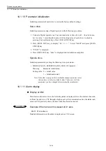
Spindle drive unit version number
Connect a Digital operator to a Converter and check the version number in the following
procedures:
1. Select a drive (dr1, dr2...: the drive number is a value, 1 more than the rotary switch set-
ting value of each drive) to check by pressing [Up] or [Down] keys. Press [DATA
ENTER] key.
2. Press [DSPL/SET] key to display "Un
□□□
, and then select "Un021".
3. Press [DATA ENTER] key to display a drive software version number.
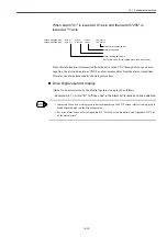
Servo/Spindle drive ACC file version number
You can check a version number of a parameter format file (ACC file) using the following
machine data for each drive.
• MD1799 FIRMWARE_VIRSION (For each axis)
Meaning:
ACC file version number (Read-only)
Axis type
00: Servo drive
01: Spindle drive
10 and 11: Reserved
b15
b10
b9
b8
b7
b0
Converter ACC version
Axis type
Drive ACC version
0-63
Refer to the following types 0-255
Summary of Contents for CNC Series
Page 1: ...Maintenance Manual Serviceman Handbook MANUAL No NCSIE SP02 19 Yaskawa Siemens CNC Series...
Page 26: ...Part 1 Hardware...
Page 38: ...System Configuration 1 2 3 Spindle motor designations 1 12...
Page 58: ...Installing the control panels 2 3 5 Installing lightning surge absorbers 2 20...
Page 62: ...Installing the motors 3 4...
Page 84: ...Connection method 4 3 2 Setting the rotary switches on the inverters and servo units 4 22...
Page 96: ...Part 2 Software...
Page 102: ...Software configuration 6 6...
Page 113: ...7 2 Network settings 7 11 8 Click on the radio button to the left of Specify an IP address...
Page 121: ...7 2 Network settings 7 19...
Page 122: ...Part 3 PLC...
Page 154: ...Part 4 Setting up and maintenance...
Page 160: ...Overview of System 10 1 2 Basic operation 10 6...
Page 204: ...How to use Digital Operation 12 2 9 Setting the password setting for write prohibit 12 32...
Page 327: ...Error and Troubleshooting 15 4...
Page 328: ...15 1 Errors without Alarm Display and Troubleshooting 15 5...
Page 329: ...Error and Troubleshooting 15 6...
Page 343: ...Maintenance and Check 16 3 3 Setting up Initializing Absolute encoder 16 14...


