


Drive set-up procedure
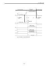
14.3.4 Emergency stop
14-66
CNC setting
• MD36060 STANDSTILL_VERO_TOL (For each axis)
Meaning: Zero
speed
Stops at the maximum torque (error cut) on the drive when the speed
falls down to or below this speed.
Setting value: [mm/min] (linear axis) or [min
-1
] (rotation axis)
• MD36610 AX_EMERGENCY_STOP_TIME (For each axis)
Meaning: Emergency
stop
standstill
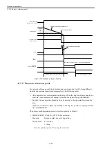
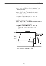
This is the duration of time to be required until the emergency stop
from the maximum speed specified with MD36210
CTRLOUT_STOP_ TIME
Setting value: [sec]
• MD36620 SERVO_DISABLE_DELAY_TIME (For each axis)
Meaning:
Duration of time from the entry of emergency stop until the servo drive
is turned off
You must configure MD36620 > MD36610.
Setting value: [sec]
Drive setting
Servo drive
• MD3356 (Pn406) EMERGENCY_STOP_TORQUE (For each axis)
Meaning: Emergency
stop
torque
Setting value: [%]
Standard setting value: 800 [%] (stop at the maximum torque)
• MD3442 (Pn516) EMERGENCY_STOP_WAIT_TIME (For each axis)
Meaning:
Emergency stop waiting time
This specifies the wait time between the input of emergency stop
(switch -> PLC -> CNC) and the emergency stop of drive (CNC ->
drive). If there is no input of the emergency stop to the drive even after
this duration of time has past, the feed axes automatically decelerate to
stop.
If you want the emergency stop to be the deceleration stop via drive,
not via CNC, specify "0" for this parameter.
Setting value: [ms]
Standard setting value: 500 [ms]
Summary of Contents for CNC Series
Page 1: ...Maintenance Manual Serviceman Handbook MANUAL No NCSIE SP02 19 Yaskawa Siemens CNC Series...
Page 26: ...Part 1 Hardware...
Page 38: ...System Configuration 1 2 3 Spindle motor designations 1 12...
Page 58: ...Installing the control panels 2 3 5 Installing lightning surge absorbers 2 20...
Page 62: ...Installing the motors 3 4...
Page 84: ...Connection method 4 3 2 Setting the rotary switches on the inverters and servo units 4 22...
Page 96: ...Part 2 Software...
Page 102: ...Software configuration 6 6...
Page 113: ...7 2 Network settings 7 11 8 Click on the radio button to the left of Specify an IP address...
Page 121: ...7 2 Network settings 7 19...
Page 122: ...Part 3 PLC...
Page 154: ...Part 4 Setting up and maintenance...
Page 160: ...Overview of System 10 1 2 Basic operation 10 6...
Page 204: ...How to use Digital Operation 12 2 9 Setting the password setting for write prohibit 12 32...
Page 327: ...Error and Troubleshooting 15 4...
Page 328: ...15 1 Errors without Alarm Display and Troubleshooting 15 5...
Page 329: ...Error and Troubleshooting 15 6...
Page 343: ...Maintenance and Check 16 3 3 Setting up Initializing Absolute encoder 16 14...


