


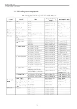
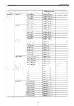

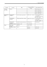


System Configuration
1.1.1 General wiring drawing
1-2
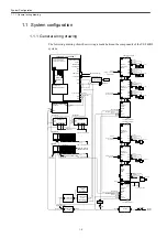
1.1 System configuration
1.1.1 General wiring drawing
The following drawing shows how wiring is made between the components of the YS 840DI
system:
IO-USB Cable
CNC Unit PCU50
200 VAC
50/60Hz
Line filter
Reactor
Yaskawa Siemens 840DI
Ethernet
USB
VGA
Operation panel unit (color LCD)
OP10FS(Standard type)
OP10FT(Touch-panel type)
X121
PS/2 Keyboard
X111
X101
X1(24 VDC IN)
I/O module
power supply
Interface module(ET200M)
Digital I/O module
(6ES7321/322/323)
PROFIBUS-DP
Emergency stop/start
condition
Circuit breaker
SVM
PS/2 MOUSE
Machine panel I/O module
PS307
PROFIBUS-DP
Machine operation panel
input/output
24 VDC
24 VDC
200 VAC
Power module
PS module 10
Power backup
battery
UPS BATTERY
24 VDC
NC keyboard
Attached to OP10F
□
Display cable
Keyboard cable
Machine operation panel
OP032S
X20
MPI
X10
MPI
LPT1
PP Module
X2
X1
X111
X222
X333
PP Module
X2
X1
X111
X222
X333
Machine panel I/O module
PROFIBUS-DP
24 VDC
24 VDC
Machine input/
output
PROFIBUS-DP
PS307
24 VDC Machine input/
output
24
VDC
24
VDC
I/O module
I/O module
200 VAC
Power backup
module
UPS module 10
200 VAC
24 VDC
Emergency stop (input)
External power
supply
200 VAC
24 VDC
Emergency stop/start
condition
HNDLE PG
PC
CARD
Separately
mounted PG
PG(Pulse)
Separately
mounted PG
PG(Pulse)
1st motor
Spindle motor
Converter
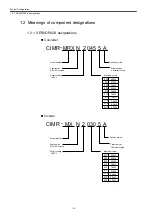
CIMR-
MRXN
Inverter
CIMR-
MXN
Servo unit
(1-axis servo)
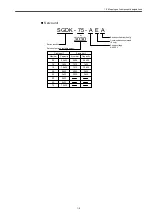
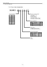
SGDK-
P N
CN5B
CN7B
P N
CN1
A1,A2
L1,L2,L3
P N
CN5B
CN7B
POWER
U,V,W,E
CN4
CN7A CN5A
P N
P N
CN7B CN5B
CN5A
CN9
Servo unit
(1-axis servo)
SGDK-
Terminating connector
POWER
CN2
CN8
CN7A CN5A
PG(Serial)
PG(Serial)
PG(Pulse or
separately mounted)
CN1
Terminating connector
PROFIBUS-DP
Bus bar
Separately
mounted PG
PG(Pulse)
CN7A CN5A
CN1
CN4
CN2
CN8
2nd motor
POWER
P N
P N
CN7B CN5B
200 VAC
200 VAC
Direct IN
Braking circuit for
the 2nd axes
Braking circuit for
the 3rd and 4th axes
Terminating
connector
CN2
PG(Serial)
Converter
CIMR-
MRXN
CN1
A1,A2
L1,L2,L3
P N
CN7B CN5B
CN5A
CN9
Terminating connector
PROFIBUS-DP
200 VAC
200 VAC
Servo unit
(2-axis servo)
SGDK-
CN12
CN18
PG(Serial)
PG(Serial)
CN7A CN5A
CN1
3rd motor
4th motor
POWER
POWER
CN28
CN22
P N
CN4
PG(Pulse)
Separately
mounted PG
CN1
CN24
CN14
Control power cable
Interface cable
Braking circuit for
the 1st axes
Separately
mounted PG
PG(Pulse)
Separately
mounted PG
PG(Pulse)
P N
CN7B CN5B
Servo unit
(2-axis servo)
SGDK-
Terminating connector
CN12
CN18
PG(Serial)
PG(Serial)
CN7A CN5A
CN1
5th motor
6th motor
POWER
POWER
CN28
CN22
P N
P N
CN7B CN5B
CN24
CN14
Direct IN
Braking circuit for the
5th and 6th axes
Bat
PROFIBUS-DP
USB
24 VDC
24 VDC
* Machine input/output
* From external power supply
* From external power supply
* From external power supply
24 VDC
PC card drive
NC ready (output)
COM1(25pin)
RS232C(D-sub9pin)
COM2(9pin)
RS232C(D-sub25pin)
Summary of Contents for CNC Series
Page 1: ...Maintenance Manual Serviceman Handbook MANUAL No NCSIE SP02 19 Yaskawa Siemens CNC Series...
Page 26: ...Part 1 Hardware...
Page 38: ...System Configuration 1 2 3 Spindle motor designations 1 12...
Page 58: ...Installing the control panels 2 3 5 Installing lightning surge absorbers 2 20...
Page 62: ...Installing the motors 3 4...
Page 84: ...Connection method 4 3 2 Setting the rotary switches on the inverters and servo units 4 22...
Page 96: ...Part 2 Software...
Page 102: ...Software configuration 6 6...
Page 113: ...7 2 Network settings 7 11 8 Click on the radio button to the left of Specify an IP address...
Page 121: ...7 2 Network settings 7 19...
Page 122: ...Part 3 PLC...
Page 154: ...Part 4 Setting up and maintenance...
Page 160: ...Overview of System 10 1 2 Basic operation 10 6...
Page 204: ...How to use Digital Operation 12 2 9 Setting the password setting for write prohibit 12 32...
Page 327: ...Error and Troubleshooting 15 4...
Page 328: ...15 1 Errors without Alarm Display and Troubleshooting 15 5...
Page 329: ...Error and Troubleshooting 15 6...
Page 343: ...Maintenance and Check 16 3 3 Setting up Initializing Absolute encoder 16 14...


