


14.2 Servo control
14-39
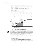
• MD6063 (Cn063) ASR_I_TIME_M_L_I (For each axis)
Meaning:
Speed control integration time (M and L gears)
Setting value: [0.1 ms]
14.2.3 Spindle servo mode
In YS 840DI system, the Spindle speed control is to be set to servo mode. The following
explains how to set fundamental Spindle drive parameters relating to servo mode.
• MD6522 (Cn522) MULTI_FUNCTION_SEL_SSC ##
Meaning:
Multi-function selection SSC
Setting value: 0 --- SSC is set to "Soft start cancelled."
1 --- SSC is set to "Servo mode."
Note: Be sure to set the parameter to "1".
• MD6064 (Cn064) ASR_P_GAIN_H_2 (For each axis)
Meaning:
Speed control proportional gain (H gear in servo mode)
Setting value: [0.1%/Hz]
• MD6065 (Cn065) ASR_I_TIME_H_2 (For each axis)
Meaning:
Speed control integration time (H gear in servo mode)
Setting value: [0.1 ms]
• MD6066 (Cn066) ASR_P_GAIN_M_L_2 (For each axis)
Meaning:
Speed control proportional gain (M and L gears in servo mode)
Setting value: [0.1%/Hz]
• MD6067 (Cn067) ASR_I_TIME_M_L_2 (For each axis)
Meaning:
Speed control integration time (M and L gears in servo mode)
Setting value: [0.1 ms]
• MD6201 (Cn201) SV_MODE_FLUX_LEVEL_H (For each axis)
Meaning:
Servo mode flux level (H gear)
Setting value: [%]
• MD6202 (Cn202) SV_BASE_SPEED_RATIO_H (For each axis)
Meaning:
Servo mode base speed ratio (H gear)
Setting value: [0.01 times]
• MD6203 (Cn203) SV_MODE_FLUX_LEVEL_M_L (For each axis)
Meaning:
Servo mode flux level (M and L gears)
Setting value: [%]
• MD6204 (Cn204) SV_BASE_SPEED_RATIO_M_L (For each axis)
Meaning:
Servo mode base speed ratio (M and L gears)
Setting value: [0.01 times]
Summary of Contents for CNC Series
Page 1: ...Maintenance Manual Serviceman Handbook MANUAL No NCSIE SP02 19 Yaskawa Siemens CNC Series...
Page 26: ...Part 1 Hardware...
Page 38: ...System Configuration 1 2 3 Spindle motor designations 1 12...
Page 58: ...Installing the control panels 2 3 5 Installing lightning surge absorbers 2 20...
Page 62: ...Installing the motors 3 4...
Page 84: ...Connection method 4 3 2 Setting the rotary switches on the inverters and servo units 4 22...
Page 96: ...Part 2 Software...
Page 102: ...Software configuration 6 6...
Page 113: ...7 2 Network settings 7 11 8 Click on the radio button to the left of Specify an IP address...
Page 121: ...7 2 Network settings 7 19...
Page 122: ...Part 3 PLC...
Page 154: ...Part 4 Setting up and maintenance...
Page 160: ...Overview of System 10 1 2 Basic operation 10 6...
Page 204: ...How to use Digital Operation 12 2 9 Setting the password setting for write prohibit 12 32...
Page 327: ...Error and Troubleshooting 15 4...
Page 328: ...15 1 Errors without Alarm Display and Troubleshooting 15 5...
Page 329: ...Error and Troubleshooting 15 6...
Page 343: ...Maintenance and Check 16 3 3 Setting up Initializing Absolute encoder 16 14...


