


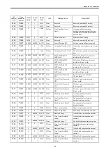


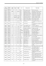


Appendix A Parameters
A-11
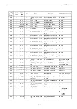
MD3070
(Pn128)
Loop gain
bank switch
0
2nd loop gain bank
selection
0
Inactive
0
1
Active
1
3rd loop gain bank
selection
0
Inactive
0
1
Active
2
4th loop gain bank
selection
0
Inactive
0
1
Active
3
Reserved
0
−
0
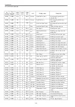
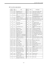
MD3079
(Pn131)
Predictive
control-
relations
0
1st predictive control
switch
0
Inactive
0
1
Active
(
Tp = 0.001
)
2
Active
(
Tp = 0.002
)
1
2nd predictive control
switch
0
Inactive
0
1
Active
(
Tp = 0.001
)
2
Active
(
Tp = 0.002
)
2
3rd predictive control
switch
0
Inactive
0
1
Active
(
Tp = 0.001
)
2
Active
(
Tp = 0.002
)
3
Reserved
0
−
0
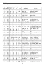
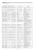
MD3200
(Pn200)
Position
control
0
Reserved
0
−
0
1
Reserved
0
−
0
2
Clearing operation
0
Clears deviation counter on base-block.
1
1
Does not clear deviation counter.
(Only CLR signal can clear.)
2
Clears deviation counter on an alarm.
3
Does not clear deviation counter.
3
Reserved
0
−
0
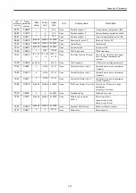
MD3207
(Pn207)
Position
control
function
switch
0
Position command filter
selection
0
Uses position command acceleration/deceleration filter.
0
1
Uses position command moving average filter.
1
Position control speed FF
0
None
0
1
Uses V-REF for speed FF input.
2
Backlash compensation
selection
0
Inactive
0
1
Corrects toward forward rotation.
2
Corrects toward reverse rotation.
3
External PG type
selection
0
Pulse encoder (Linear scale)
0
1
Pulse encoder (Rotary)
2
Serial encoder
3
MP scale
User
Constant
No.
Digit
Name
Setting
Description
Factory
default
setting
Summary of Contents for CNC Series
Page 1: ...Maintenance Manual Serviceman Handbook MANUAL No NCSIE SP02 19 Yaskawa Siemens CNC Series...
Page 26: ...Part 1 Hardware...
Page 38: ...System Configuration 1 2 3 Spindle motor designations 1 12...
Page 58: ...Installing the control panels 2 3 5 Installing lightning surge absorbers 2 20...
Page 62: ...Installing the motors 3 4...
Page 84: ...Connection method 4 3 2 Setting the rotary switches on the inverters and servo units 4 22...
Page 96: ...Part 2 Software...
Page 102: ...Software configuration 6 6...
Page 113: ...7 2 Network settings 7 11 8 Click on the radio button to the left of Specify an IP address...
Page 121: ...7 2 Network settings 7 19...
Page 122: ...Part 3 PLC...
Page 154: ...Part 4 Setting up and maintenance...
Page 160: ...Overview of System 10 1 2 Basic operation 10 6...
Page 204: ...How to use Digital Operation 12 2 9 Setting the password setting for write prohibit 12 32...
Page 327: ...Error and Troubleshooting 15 4...
Page 328: ...15 1 Errors without Alarm Display and Troubleshooting 15 5...
Page 329: ...Error and Troubleshooting 15 6...
Page 343: ...Maintenance and Check 16 3 3 Setting up Initializing Absolute encoder 16 14...


