


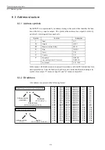


8.3 Address structure
8-5
8.3.3 Addressing of input, output, bit memory, and data bits
Each bit is identified by the address of a byte to which it belongs and its own address relative
to that byte (each byte consists of 8 bits). Thus a bit is expressed in the following format:
[address symbol][byte address]. [bit address] (e.g., I1.2)
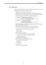
Address symbol
A bit address starts with a symbol such as I, Q, M, or DBX.
The symbol for a data bit is DBX (e.g., DBX1.2).
Bit address
The bit address part of a bit address is the numerical part after the period (.). It is repre-
sented by a digit between 0 and 7 (the 8 bits make up a byte).
Byte address
The byte address part of a bit address is the numerical part after the address symbol and
before the period (.). It is represented by an integer in the decimal notation (0, 1, 2, 3, 4, 5,
6, 7, 8, 9, 10, 11, ...). As a byte is expressed as a combination of an address symbol and a
byte address, I1.2 and Q1.2 are two different bits.
8.3.4 Addressing of timers and counters
A timer or counter is expressed as a combination of an address symbol and a byte address
(with no bit address). Thus a timer or counter is expressed in the following format:
[address symbol][number] (e.g., T10)
The number is any integer in the decimal notation (starting with 0). The maximum allow-
able value of the number depends on the CPU used.
Summary of Contents for CNC Series
Page 1: ...Maintenance Manual Serviceman Handbook MANUAL No NCSIE SP02 19 Yaskawa Siemens CNC Series...
Page 26: ...Part 1 Hardware...
Page 38: ...System Configuration 1 2 3 Spindle motor designations 1 12...
Page 58: ...Installing the control panels 2 3 5 Installing lightning surge absorbers 2 20...
Page 62: ...Installing the motors 3 4...
Page 84: ...Connection method 4 3 2 Setting the rotary switches on the inverters and servo units 4 22...
Page 96: ...Part 2 Software...
Page 102: ...Software configuration 6 6...
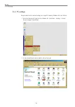
Page 113: ...7 2 Network settings 7 11 8 Click on the radio button to the left of Specify an IP address...
Page 121: ...7 2 Network settings 7 19...
Page 122: ...Part 3 PLC...
Page 154: ...Part 4 Setting up and maintenance...
Page 160: ...Overview of System 10 1 2 Basic operation 10 6...
Page 204: ...How to use Digital Operation 12 2 9 Setting the password setting for write prohibit 12 32...
Page 327: ...Error and Troubleshooting 15 4...
Page 328: ...15 1 Errors without Alarm Display and Troubleshooting 15 5...
Page 329: ...Error and Troubleshooting 15 6...
Page 343: ...Maintenance and Check 16 3 3 Setting up Initializing Absolute encoder 16 14...


