


11.1 Drive Parameter Screen Operation
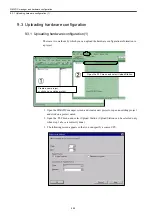
11-3
11.1.2 Screen Configuration
Screen Configuration
The configuration of drive parameters are displayed as follows.
①
②
③
④
⑤
⑥
⑦
⑧
⑨
⑩
⑬
⑭
⑮
(F1)
(F2)
(F3)
(F4)
(F5)
(F6)
(F7)
(F8)
(F9)
(F10)
(F11)
(F12)
(F13)
(F14)
(F15)
(F16)
⑫
⑪
⑯
⑰
①:
Parameter number
②:
Name of parameter
③:
Selection display
④:
Parameter setting value
⑤:
Name of axis
⑥:
Drive number
⑦:
Conditions of validity
⑧:
Unit
⑨:
Description of selected parameter
⑩:
Drive diagnosis screen switching key
⑪:
Screen switching key
⑫:
Target axis switching key
⑬:
Target axis switching key
⑭:
Target axis directly-switching key
⑮:
Search key
⑯:
Continuing search key
⑰:
Update key
Summary of Contents for CNC Series
Page 1: ...Maintenance Manual Serviceman Handbook MANUAL No NCSIE SP02 19 Yaskawa Siemens CNC Series...
Page 26: ...Part 1 Hardware...
Page 38: ...System Configuration 1 2 3 Spindle motor designations 1 12...
Page 58: ...Installing the control panels 2 3 5 Installing lightning surge absorbers 2 20...
Page 62: ...Installing the motors 3 4...
Page 84: ...Connection method 4 3 2 Setting the rotary switches on the inverters and servo units 4 22...
Page 96: ...Part 2 Software...
Page 102: ...Software configuration 6 6...
Page 113: ...7 2 Network settings 7 11 8 Click on the radio button to the left of Specify an IP address...
Page 121: ...7 2 Network settings 7 19...
Page 122: ...Part 3 PLC...
Page 154: ...Part 4 Setting up and maintenance...
Page 160: ...Overview of System 10 1 2 Basic operation 10 6...
Page 204: ...How to use Digital Operation 12 2 9 Setting the password setting for write prohibit 12 32...
Page 327: ...Error and Troubleshooting 15 4...
Page 328: ...15 1 Errors without Alarm Display and Troubleshooting 15 5...
Page 329: ...Error and Troubleshooting 15 6...
Page 343: ...Maintenance and Check 16 3 3 Setting up Initializing Absolute encoder 16 14...


