


14.1 Fundamental settings
14-21
• MD30260 ABS_INC_RATIO [1] (For each axis)
Meaning:
Ratio to External encoder absolute position data from drive to CNC
Standard setting value: 1
• MD31000 ENC_LINEAR [1] (For each axis)
Meaning:
External encoder type (rotary encoder/linear scale) setting
Setting value: 0 --- Rotary encoder
1 --- Linear scale
• MD31010 ENC_GRID_POINT_DIST [1] (For each axis)
Meaning: Linear
scale
resolution
Setting value: [mm]
• MD31020 ENC_RESOL [1] (For each axis)
Meaning:
The number of separate rotary encoder pulses
The setting value is compared with a value read from a drive. If the val-
ues are different each other, an alarm is issued.
Setting value: The number of separate rotary encoder pulses (4-multiplication values)/
MD31025 [1]
Refer to Table 14.3.
• MD31025 ENC_PULSE_MULT [1] (For each axis)
Meaning:
External encoder pulse magnification
Setting value: Linear scale --- 1
Rotary encoder --- 4 (Refer to the table below)
• MD31040 ENC_IS_DIRECT [1] (For each axis)
Meaning: External
encoder
active/inactive
Setting value: 0 --- Inactive
1 --- Active
• MD32110 ENC_FEEDBACK_POL [1] (For each axis)
Meaning:
Separate rotary encoder rotation direction
Setting value: 0 or 1 --- forward rotation
(-1 --- Reverse rotation)
Note: (Note) Set up External encoder reverse rotation connection at the
drive side. Be sure to set this parameter to "0" or "1".
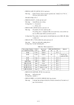
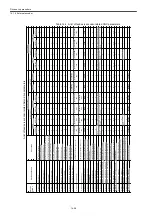
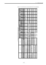
Table 14.3
List of separate rotary encoders
Number of pulses
(4-multiplication value)
Serial/
Pulse
Servo axis/
Spindle
MD31020
[1]
MD31025
[1]
Remarks
4096
Pulses
Spindle
1024
4
32768
Pulses
Servo
8192
4
360000
Pulses
Servo
90000
4
Spindle-embedded C
axis is excluded from
targets because 19-bit
encoders are used for
the time being.
Summary of Contents for CNC Series
Page 1: ...Maintenance Manual Serviceman Handbook MANUAL No NCSIE SP02 19 Yaskawa Siemens CNC Series...
Page 26: ...Part 1 Hardware...
Page 38: ...System Configuration 1 2 3 Spindle motor designations 1 12...
Page 58: ...Installing the control panels 2 3 5 Installing lightning surge absorbers 2 20...
Page 62: ...Installing the motors 3 4...
Page 84: ...Connection method 4 3 2 Setting the rotary switches on the inverters and servo units 4 22...
Page 96: ...Part 2 Software...
Page 102: ...Software configuration 6 6...
Page 113: ...7 2 Network settings 7 11 8 Click on the radio button to the left of Specify an IP address...
Page 121: ...7 2 Network settings 7 19...
Page 122: ...Part 3 PLC...
Page 154: ...Part 4 Setting up and maintenance...
Page 160: ...Overview of System 10 1 2 Basic operation 10 6...
Page 204: ...How to use Digital Operation 12 2 9 Setting the password setting for write prohibit 12 32...
Page 327: ...Error and Troubleshooting 15 4...
Page 328: ...15 1 Errors without Alarm Display and Troubleshooting 15 5...
Page 329: ...Error and Troubleshooting 15 6...
Page 343: ...Maintenance and Check 16 3 3 Setting up Initializing Absolute encoder 16 14...


