
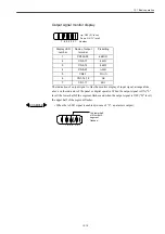


How to use Digital Operation
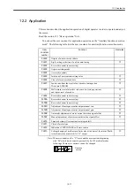
12.2.8 Motor current detection signal offset adjustment
12-28
12.2.8 Motor current detection signal offset adjustment
The offset adjustment for motor current detection signal does generally require no customer
adjustment because the YSNC completed the adjustment before shipping. However, if you
need more precise accuracy, for example, in case that you recognize the torque ripple based
on the current offset is excessively large, or in case that you want to reduce the torque ripple
furthermore, this function is available.
This is the procedure for the automatic and manual adjustment for offset.
If you carelessly initiate this function, especially manual adjustment, that may deteriorate the feature.
When you determine the torque ripple is obviously large in comparison to other
SERVOPACK
, you
may execute the automatic adjustment for offset.
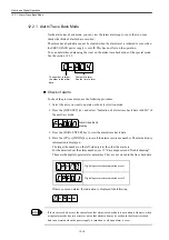
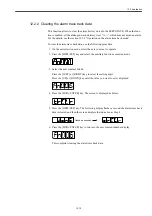
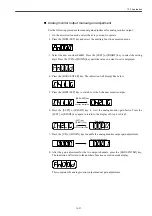
Motor current detection signal offset automatic adjustment
Use the following steps for the motor current detection signal offset automatic adjustment.
The automatic adjustment is available only when the main circuit power supply is turned on and simul-
taneously the servo drive is cut off.
1. On the axis selection mode, select the axis you want to operate.
2. Press the DSPL/SET key to select the auxiliary function execution mode.
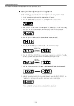
3. Select the user constant Fn00E. Press the [LEFT] or [RIGHT] key to select the setting
digit. Press the [UP] or [DOWN] key until the value you want to set is displayed.
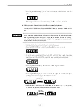
4. Press the [DATA/ENTER] key. The indication displays as below.
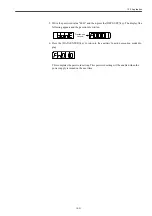
5. Press the [DSPL/SET] key. The following indication displays and the offset automatic
adjustment is executed.
IMPORTANT
Flashes for
a second.
Summary of Contents for CNC Series
Page 1: ...Maintenance Manual Serviceman Handbook MANUAL No NCSIE SP02 19 Yaskawa Siemens CNC Series...
Page 26: ...Part 1 Hardware...
Page 38: ...System Configuration 1 2 3 Spindle motor designations 1 12...
Page 58: ...Installing the control panels 2 3 5 Installing lightning surge absorbers 2 20...
Page 62: ...Installing the motors 3 4...
Page 84: ...Connection method 4 3 2 Setting the rotary switches on the inverters and servo units 4 22...
Page 96: ...Part 2 Software...
Page 102: ...Software configuration 6 6...
Page 113: ...7 2 Network settings 7 11 8 Click on the radio button to the left of Specify an IP address...
Page 121: ...7 2 Network settings 7 19...
Page 122: ...Part 3 PLC...
Page 154: ...Part 4 Setting up and maintenance...
Page 160: ...Overview of System 10 1 2 Basic operation 10 6...
Page 204: ...How to use Digital Operation 12 2 9 Setting the password setting for write prohibit 12 32...
Page 327: ...Error and Troubleshooting 15 4...
Page 328: ...15 1 Errors without Alarm Display and Troubleshooting 15 5...
Page 329: ...Error and Troubleshooting 15 6...
Page 343: ...Maintenance and Check 16 3 3 Setting up Initializing Absolute encoder 16 14...


