


SIMATIC manager and hardware configuration
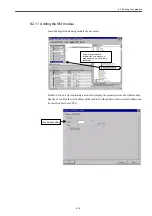
9.2.7 Adding the CPU module
9-10
9.2.7 Adding the CPU module
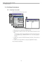
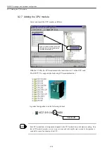
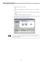
Select and insert the CPU module as follows:
With the S7-300, the CPU module must be inserted in slot 2 of the CPU rack.
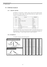
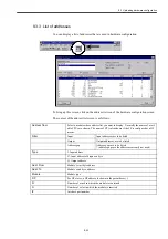
The STEP7 V5.x supports the following CPU module families:
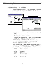
A product designation is in the following format:
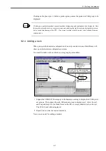
Each CPU module has its designation displayed in the CPU module list in the hardware catalog. Note
that a CPU module may have two or more versions, and selecting the right version by designation is
essential to correct functioning of the CPU.
挿入先の
2
番スロットを指定して
CPU
モジュールをダブルクリック。
あるいはモジュールを選択してドラ
ッグアンドドロップ
Select slot 2 and double-click on the
CPU module, or drag and drop the
CPU module into slot 2.
Version ID
INFO
Summary of Contents for CNC Series
Page 1: ...Maintenance Manual Serviceman Handbook MANUAL No NCSIE SP02 19 Yaskawa Siemens CNC Series...
Page 26: ...Part 1 Hardware...
Page 38: ...System Configuration 1 2 3 Spindle motor designations 1 12...
Page 58: ...Installing the control panels 2 3 5 Installing lightning surge absorbers 2 20...
Page 62: ...Installing the motors 3 4...
Page 84: ...Connection method 4 3 2 Setting the rotary switches on the inverters and servo units 4 22...
Page 96: ...Part 2 Software...
Page 102: ...Software configuration 6 6...
Page 113: ...7 2 Network settings 7 11 8 Click on the radio button to the left of Specify an IP address...
Page 121: ...7 2 Network settings 7 19...
Page 122: ...Part 3 PLC...
Page 154: ...Part 4 Setting up and maintenance...
Page 160: ...Overview of System 10 1 2 Basic operation 10 6...
Page 204: ...How to use Digital Operation 12 2 9 Setting the password setting for write prohibit 12 32...
Page 327: ...Error and Troubleshooting 15 4...
Page 328: ...15 1 Errors without Alarm Display and Troubleshooting 15 5...
Page 329: ...Error and Troubleshooting 15 6...
Page 343: ...Maintenance and Check 16 3 3 Setting up Initializing Absolute encoder 16 14...


