


SIMATIC manager and hardware configuration
9.2.5 S7-300 rack
9-8
9.2.5 S7-300 rack
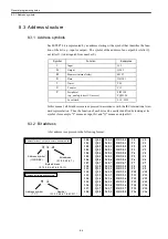
The S7-300 rack can have up to 11 slots numbered 1-11. Slots 1-3 can contain only a spe-
cific module: slot 1 can contain a power supply module (PS), slot 2 a CPU module (CPU),
and slot 3 an interface module (IM). Thus, if no PS or IM module is used, the corresponding
slot must be left empty.
Slot 4 and later slots, however, may contain any of the SM module (digital or analog I/O),
communication module (CP), and function module (FM). Slot 4 and later slots must not be
left empty. A supplementary rack must have slots 1 and 2 left empty. It is recommended
that the FM or CP module be inserted in the main rack, as it cannot always be inserted in a
supplementary rack.
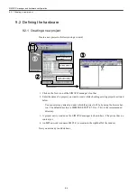
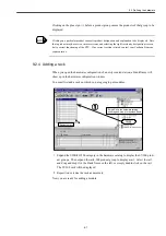
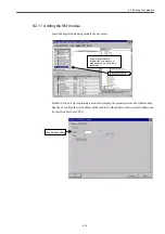
9.2.6 Adding the power supply module
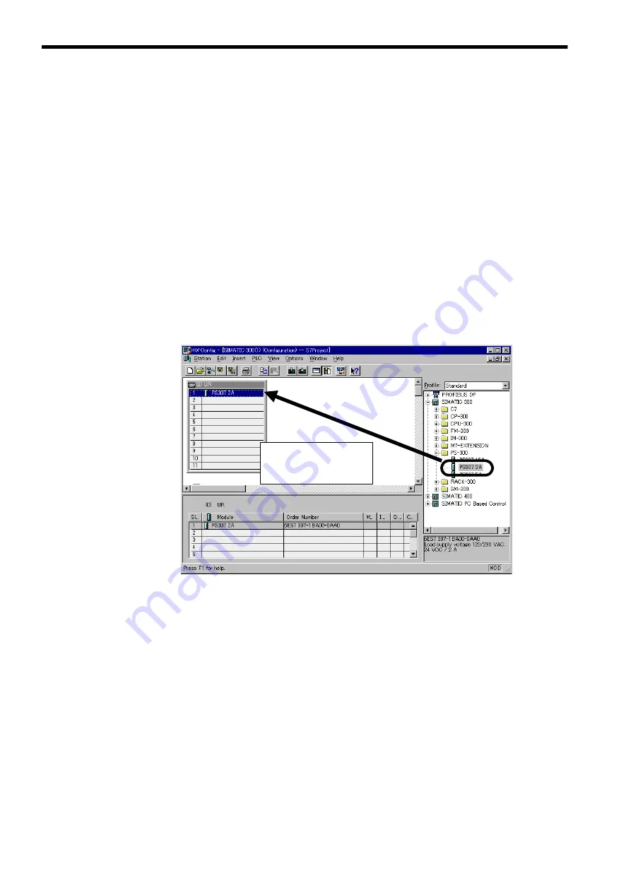
Insert the power supply module first in slot 1.
When adding the power supply module, CPU module, or I/O module to the rack, you can
use one of the two methods: slot specification and drag-and-drop.
Slot specification method
Select a target slot and double-click on the module as follows:
1. Click on a slot of the rack to which you want to add a module of your choice. The
selected slot is indicated by blue background.
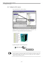
2. Click on the module in the hardware catalog. The selected module is indicated by blue
background.
3. Double-click on the same module. The module is automatically inserted in the selected
slot.
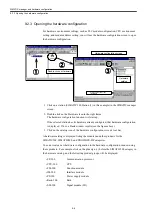
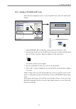
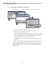
挿入先のスロットを指定して
モジュールをダブルクリック、
あるいはモジュールを選択し
てドラッグアンドドロップ
Select a target slot and
double-click on the module, or
drag and drop the module into
a target slot.
Summary of Contents for CNC Series
Page 1: ...Maintenance Manual Serviceman Handbook MANUAL No NCSIE SP02 19 Yaskawa Siemens CNC Series...
Page 26: ...Part 1 Hardware...
Page 38: ...System Configuration 1 2 3 Spindle motor designations 1 12...
Page 58: ...Installing the control panels 2 3 5 Installing lightning surge absorbers 2 20...
Page 62: ...Installing the motors 3 4...
Page 84: ...Connection method 4 3 2 Setting the rotary switches on the inverters and servo units 4 22...
Page 96: ...Part 2 Software...
Page 102: ...Software configuration 6 6...
Page 113: ...7 2 Network settings 7 11 8 Click on the radio button to the left of Specify an IP address...
Page 121: ...7 2 Network settings 7 19...
Page 122: ...Part 3 PLC...
Page 154: ...Part 4 Setting up and maintenance...
Page 160: ...Overview of System 10 1 2 Basic operation 10 6...
Page 204: ...How to use Digital Operation 12 2 9 Setting the password setting for write prohibit 12 32...
Page 327: ...Error and Troubleshooting 15 4...
Page 328: ...15 1 Errors without Alarm Display and Troubleshooting 15 5...
Page 329: ...Error and Troubleshooting 15 6...
Page 343: ...Maintenance and Check 16 3 3 Setting up Initializing Absolute encoder 16 14...


