


Drive set-up procedure
14.3.10 Gantry control
14-82
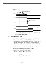
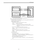
Setup process for the return to reference point for the gantry axis
incremental encoder
1. Specify "0.001" with MD37110 : GANTRY POS TOL WARNING (synchronicity devi-
ation warning output level position deviation). (This prevents the slave axis from being
synchronized at the first return to reference point.)
2. After supplying power to the servo drives, initiate the return to reference point on REF
mode.
First the return to reference point for master axis is enabled and then that for slave axis
is enabled.(Here you have an alarm output, but ignore the alarm and go on to the follow-
ing process.)
3. On the diagnosis (service display) screen, check the master axis "measurement position
for measurement system 1" (for motor encoder) or "measurement position for measure-
ment system 2" (for separately mounted encoder) after the slave axis return to reference
point is completed.
4. Reverse the sign of the value you just checked on Step 3 and enter the value with the
reversed sign into the slave axis with MD34080 [0] or [1] : REEP_MOVE_DIST (return
to reference point travel distance). ([0] for the motor encoder control, and [1] for the
separately mounted encoder)
5. Check that the gantry axis moves synchronously.
6. Specify a proper value with MD37110.
7. Initiate NCK Reset. Check the return to reference point motion again and then complete
the process.
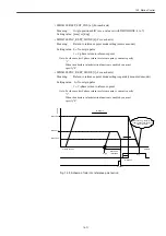
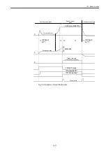
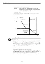
Supposing the C phase searching direction as the reverse setting (MD34050 = 1), set the return to ref-
erence point direction (MD34010) for slave axis and C phase searching direction (MD34050) for the
opposite direction to the master axis when the position of encoder C phase is ahead of the origin dog in
the return to reference point direction (direction setting for MD34010) for the master axis.
INFO
Summary of Contents for CNC Series
Page 1: ...Maintenance Manual Serviceman Handbook MANUAL No NCSIE SP02 19 Yaskawa Siemens CNC Series...
Page 26: ...Part 1 Hardware...
Page 38: ...System Configuration 1 2 3 Spindle motor designations 1 12...
Page 58: ...Installing the control panels 2 3 5 Installing lightning surge absorbers 2 20...
Page 62: ...Installing the motors 3 4...
Page 84: ...Connection method 4 3 2 Setting the rotary switches on the inverters and servo units 4 22...
Page 96: ...Part 2 Software...
Page 102: ...Software configuration 6 6...
Page 113: ...7 2 Network settings 7 11 8 Click on the radio button to the left of Specify an IP address...
Page 121: ...7 2 Network settings 7 19...
Page 122: ...Part 3 PLC...
Page 154: ...Part 4 Setting up and maintenance...
Page 160: ...Overview of System 10 1 2 Basic operation 10 6...
Page 204: ...How to use Digital Operation 12 2 9 Setting the password setting for write prohibit 12 32...
Page 327: ...Error and Troubleshooting 15 4...
Page 328: ...15 1 Errors without Alarm Display and Troubleshooting 15 5...
Page 329: ...Error and Troubleshooting 15 6...
Page 343: ...Maintenance and Check 16 3 3 Setting up Initializing Absolute encoder 16 14...


