


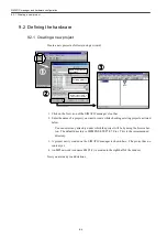


General programming notes
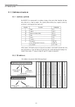
8.3.1 Address symbols
8-4
8.3 Address structure
8.3.1 Address symbols
Each STEP7 bit is represented by an address starting with a symbol that identifies the func-
tion of the bit (e.g., input or output). The symbol of the address of an output bit is letter Q,
not letter O (to distinguish from number 0).
In this manual, all bit addresses are expressed in accordance with the IEC international stan-
dard representation. Thus the function of each bit can be easily identified by looking at its
symbol (for example, "I" means an input bit, and "Q" means an output bit).
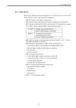
8.3.2 Bit address
A bit address is expressed in the following format:
Symbol
Function
Examples
I
Input
I5.2
Q
Output
Q54.3
M
Memory (internal relay)
M12.7
D
Data
DBX1.1
T
Timer
T24
C
Counter
C15
P
Peripheral
(e.g., analog, direct I/O access)
PIW128
PQW128
Local stack
L1.2, LW2
Byte address
Bit address
Address symbol
I 0.0
I 0.1
I 0.2
I 0.3
I 0.4
I 0.5
I 0.6
I 0.7
I 1.0
I 1.1
I 1.2
I 1.3
I 1.4
I 1.5
I 1.6
I 1.7
I 2.0
:
Q 0.0
Q 0.1
Q 0.2
Q 0.3
Q 0.4
Q 0.5
Q 0.6
Q 0.7
Q 1.0
Q 1.1
Q 1.2
Q 1.3
Q 1.4
Q 1.5
Q 1.6
Q 1.7
Q 2.0
:
M 0.0
M 0.1
M 0.2
M 0.3
M 0.4
M 0.5
M 0.6
M 0.7
M 1.0
M 1.1
M 1.2
M 1.3
M 1.4
M 1.5
M 1.6
M 1.7
M 2.0
:
T 0
T 1
T 2
T 3
T 4
T 5
T 6
T 7
T 8
T 9
T 10
T 11
T 12
T 13
T 14
T 15
T 16
:
C 0
C 1
C 2
C 3
C 4
C 5
C 6
C 7
C 8
C 9
C 10
C 11
C 12
C 13
C 14
C 15
C 16
:
DBX 0.0
DBX 0.1
DBX 0.2
DBX 0.3
DBX 0.4
DBX 0.5
DBX 0.6
DBX 0.7
DBX 1.0
DBX 1.1
DBX 1.2
DBX 1.3
DBX 1.4
DBX 1.5
DBX 1.6
DBX 1.7
DBX 2.0
:
入力、出力、ビットメモリ、データの表記
Address for input, output, memory, and data bits
T 1
Address symbol
Number
Address for timers and counters
(0,1,2,3,4,5,6,7,8,9,10,11)
(0,1,2,3,4,5,6,7,)
(I,Q,N,DBX)
(0,1,2,3,4,5,6,7,8,9,10,11)
(T,C)
I 1.2
Summary of Contents for CNC Series
Page 1: ...Maintenance Manual Serviceman Handbook MANUAL No NCSIE SP02 19 Yaskawa Siemens CNC Series...
Page 26: ...Part 1 Hardware...
Page 38: ...System Configuration 1 2 3 Spindle motor designations 1 12...
Page 58: ...Installing the control panels 2 3 5 Installing lightning surge absorbers 2 20...
Page 62: ...Installing the motors 3 4...
Page 84: ...Connection method 4 3 2 Setting the rotary switches on the inverters and servo units 4 22...
Page 96: ...Part 2 Software...
Page 102: ...Software configuration 6 6...
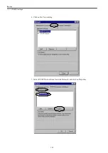
Page 113: ...7 2 Network settings 7 11 8 Click on the radio button to the left of Specify an IP address...
Page 121: ...7 2 Network settings 7 19...
Page 122: ...Part 3 PLC...
Page 154: ...Part 4 Setting up and maintenance...
Page 160: ...Overview of System 10 1 2 Basic operation 10 6...
Page 204: ...How to use Digital Operation 12 2 9 Setting the password setting for write prohibit 12 32...
Page 327: ...Error and Troubleshooting 15 4...
Page 328: ...15 1 Errors without Alarm Display and Troubleshooting 15 5...
Page 329: ...Error and Troubleshooting 15 6...
Page 343: ...Maintenance and Check 16 3 3 Setting up Initializing Absolute encoder 16 14...


