


Drive set-up procedure
14.3.2 Acceleration/Deceleration
14-60
• MD32300 MAX_AX_ACCEL (For each axis)
Meaning: Acc./dec.
rate
Setting value: [mm/sec
2
] or [deg/sec
2
]
Note: Applied for G00 and G01.
• MD32310 MAX_ACCEL_OVL_FACTOR (For each axis)
Meaning:
Corner speed change
Setting value: [percentage]
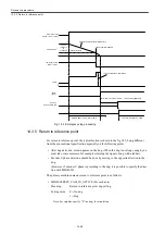
The speed differences of each axis according to changes of orientation
of block boundary are controlled by the percentage for acc./dec. rate
(MD32300). Generally set the value to "1.01". This value is equal to
the conventional acceleration at the corner. For further reduction of
shocks at the corner, output G642 command or decrease the value with
MD32431.
Note: Applied for G00 and G01.
Standard setting value: 0.01
• MD32431 MAX_AX_JERK (For each axis)
Meaning:
Axis-specific acc./dec. jerk (acceleration rate)
Setting value: [mm/sec
3
] or [deg/sec
3
]
Note: Applied for G00 and G01.
Do not use MD32410 AX_JERK_TIME together with pre-interpola-
tion acc./dec., because it is post-interpolation acc./dec. jerk and
affects machining profile errors.
Specify a larger value (ex. 1,000,000 for the initial value) with
MD20600 MAX_AX_JERK than the value with MD32431.
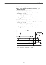
• MD32432 PATH_TRANS_JERK_LIM (For each axis)
Meaning:
Jerk limit between blocks
Jerk setting for controlling the acceleration rate differences which
occur according to the change of radius of curvature on the boundary
of blocks such as continuous arc blocks.
Setting value: [mm/sec
3
] or [deg/sec
3
]
Standard setting value: Identical to MD32431
• MD32434 G00_ACCEL_FACTOR (For each axis)
Meaning:
Acceleration factor for G00. Percentage of acceleration for MD32300.
Setting value: [percentage]
• MD32435 G00_JERK_FACTOR (For each axis)
Meaning:
Acc./dec. jerk for G00. Percentage of acc./dec. jerk for MD32431.
Setting value: [percentage]
Summary of Contents for CNC Series
Page 1: ...Maintenance Manual Serviceman Handbook MANUAL No NCSIE SP02 19 Yaskawa Siemens CNC Series...
Page 26: ...Part 1 Hardware...
Page 38: ...System Configuration 1 2 3 Spindle motor designations 1 12...
Page 58: ...Installing the control panels 2 3 5 Installing lightning surge absorbers 2 20...
Page 62: ...Installing the motors 3 4...
Page 84: ...Connection method 4 3 2 Setting the rotary switches on the inverters and servo units 4 22...
Page 96: ...Part 2 Software...
Page 102: ...Software configuration 6 6...
Page 113: ...7 2 Network settings 7 11 8 Click on the radio button to the left of Specify an IP address...
Page 121: ...7 2 Network settings 7 19...
Page 122: ...Part 3 PLC...
Page 154: ...Part 4 Setting up and maintenance...
Page 160: ...Overview of System 10 1 2 Basic operation 10 6...
Page 204: ...How to use Digital Operation 12 2 9 Setting the password setting for write prohibit 12 32...
Page 327: ...Error and Troubleshooting 15 4...
Page 328: ...15 1 Errors without Alarm Display and Troubleshooting 15 5...
Page 329: ...Error and Troubleshooting 15 6...
Page 343: ...Maintenance and Check 16 3 3 Setting up Initializing Absolute encoder 16 14...


