


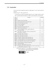


12.1 Basic operation
12-7
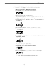
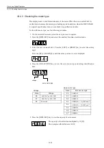
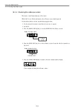
Position Control Mode
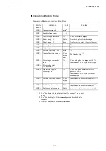
The indication of bit data and codes is shown in the following tables.
Table 12.3 The bit data indication on the position control mode
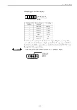
Table 12.4 Indication of code on position control mode
Bit data
Indication
Control power supply
ON
Lights when the SERVOPACK control power supply is turned
on.
Base block
Lights when the base block is enabled.
Goes out when the servo drive is turned on.
Positioning
completion
Lights when the deviation between the reference position and the
actual motor position is equal or below the specified value.
Goes out when the value is lower than the specified value.
Specified value: Set with Pn500 (Standard value is 7 pulses.)
/TGON
Lights when the motor speed is higher than the specified value.
Goes out when the speed is lower than the specified value.
Specified value: Set with Pn502 (Standard value is 20 min
-1
.)
Reference pulse is
inputting
Lights when the reference pulse is being inputting.
Goes out when the reference pulse is not being inputting.
Clear signal
Lights when the clear signal is being inputting.
Goes out when the clear signal is not being inputting.
Power ready
Lights when the main circuit power supply is normal.
Goes out when the main circuit power supply is off.
Code
Indication
Base block is enabled.
Servo drive is turned off. (Motor is not supplied with power.)
In operation
Servo drive is turned on. (Motor is supplied with power.)
Alarm state
Displays the alarm number.
:
Code
Bit data
Positioning
completion
Base block
Control power
supply is ON.
Reference pulse is
inputting
TGON
Power is ready
Clear signal is
inputting
Summary of Contents for CNC Series
Page 1: ...Maintenance Manual Serviceman Handbook MANUAL No NCSIE SP02 19 Yaskawa Siemens CNC Series...
Page 26: ...Part 1 Hardware...
Page 38: ...System Configuration 1 2 3 Spindle motor designations 1 12...
Page 58: ...Installing the control panels 2 3 5 Installing lightning surge absorbers 2 20...
Page 62: ...Installing the motors 3 4...
Page 84: ...Connection method 4 3 2 Setting the rotary switches on the inverters and servo units 4 22...
Page 96: ...Part 2 Software...
Page 102: ...Software configuration 6 6...
Page 113: ...7 2 Network settings 7 11 8 Click on the radio button to the left of Specify an IP address...
Page 121: ...7 2 Network settings 7 19...
Page 122: ...Part 3 PLC...
Page 154: ...Part 4 Setting up and maintenance...
Page 160: ...Overview of System 10 1 2 Basic operation 10 6...
Page 204: ...How to use Digital Operation 12 2 9 Setting the password setting for write prohibit 12 32...
Page 327: ...Error and Troubleshooting 15 4...
Page 328: ...15 1 Errors without Alarm Display and Troubleshooting 15 5...
Page 329: ...Error and Troubleshooting 15 6...
Page 343: ...Maintenance and Check 16 3 3 Setting up Initializing Absolute encoder 16 14...


