


How to use Digital Operation
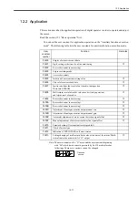
12.1.7 User Constant Setting Mode
12-10
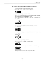
Here is the description about indication of setting value. There are two types of user constant
display.
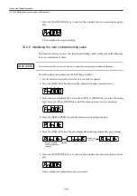
For the function selection user constant, since the value of each digit have individual mean-
ings, you can only change the value on each digit respectively. In addition, each digit dis-
plays only the value available in the setting range.
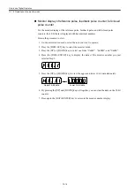
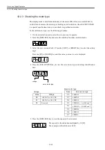
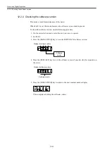
Definition of display of function selection user constant
The function selection user constant has individual meanings for each digit.
For example, the number on the right end of the user constant "Pn000" is indicated
"Pn000.0".
The individual "digit" of function selection user constant setting value is defined as followings. The
"example of display" shows the user constant display according to this "digit" definition of the setting
value.
• Setting value
• Indication of user constant
Pn000.0 ••••• Shows the value which is indicated on the "0" digit of the setting value of the user
constant "Pn000".
Pn000.1 ••••• Shows the value which is indicated on the "1" digit of the setting value of the user
constant "Pn000".
Pn000.2 ••••• Shows the value which is indicated on the "2" digit of the setting value of the user
constant "Pn000".
Pn000.3 ••••• Shows the value which is indicated on the "3" digit of the setting value of the user
constant "Pn000".
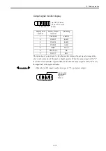
An example of the function selection
user constant
‥‥
Displayed with hexadecimal
number per digit.
An example of the constant setting
user constant
‥‥
Displayed with 5-digit
decimal number.
IMPORTANT
digit 0
digit 1
digit 2
digit 3
Summary of Contents for CNC Series
Page 1: ...Maintenance Manual Serviceman Handbook MANUAL No NCSIE SP02 19 Yaskawa Siemens CNC Series...
Page 26: ...Part 1 Hardware...
Page 38: ...System Configuration 1 2 3 Spindle motor designations 1 12...
Page 58: ...Installing the control panels 2 3 5 Installing lightning surge absorbers 2 20...
Page 62: ...Installing the motors 3 4...
Page 84: ...Connection method 4 3 2 Setting the rotary switches on the inverters and servo units 4 22...
Page 96: ...Part 2 Software...
Page 102: ...Software configuration 6 6...
Page 113: ...7 2 Network settings 7 11 8 Click on the radio button to the left of Specify an IP address...
Page 121: ...7 2 Network settings 7 19...
Page 122: ...Part 3 PLC...
Page 154: ...Part 4 Setting up and maintenance...
Page 160: ...Overview of System 10 1 2 Basic operation 10 6...
Page 204: ...How to use Digital Operation 12 2 9 Setting the password setting for write prohibit 12 32...
Page 327: ...Error and Troubleshooting 15 4...
Page 328: ...15 1 Errors without Alarm Display and Troubleshooting 15 5...
Page 329: ...Error and Troubleshooting 15 6...
Page 343: ...Maintenance and Check 16 3 3 Setting up Initializing Absolute encoder 16 14...


