


14.1 Fundamental settings
14-15
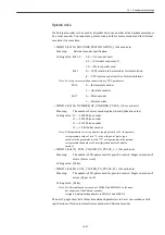
• MD30260 ABS_INC_RATIO [0] (For each axis)
Meaning:
Ratio of motor encoder absolute position data, from drive to CNC, to
Motor encoder position data.
Standard setting value: 1
• MD30300 IS_ROT_AX (For each axis) ##
Meaning:
Linear/Rotary axis setting
Setting value: 0 --- Linear axis
1 --- Rotary axis
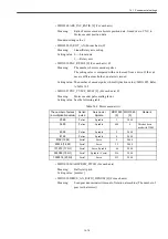
• MD31020 ENC_RESOL [0] (For each axis) ##
Meaning:
The number of motor encoder pulses
The setting value is compared with a value read from a drive. If the val-
ues are different each other, an alarm is issued.
Setting value: The number of encoder pulses (4-multiplication value) /MD31025. Refer
to Table 14.2.
• MD31025 ENC_PULCE_MULT [0] (For each axis) ##
Meaning:
Motor encoder pulse scaling factor
Setting value: See the following table.
• MD31030 LEADSCREW_PITCH (For each axis)
Meaning:
Ball screw pitch
Setting value: [mm/rev]
• MD31050 DRIVE_AX_RATIO_DENOM [0] (For each axis)
Meaning:
Load gear denominator (Amount of rotation at machine (The number of
gear teeth at motor))
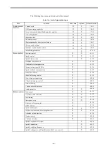
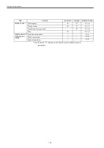
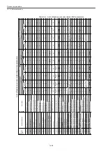
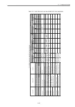
Table 14.2
Motor encoder list
The number of pulses
(4-multiplication value)
Serial/
pulse
Servo axis/
Spindle
MD31020
[0]
MD31025
[0]
Remark
2048
Pulses
Spindle
1
2048
3600
Pulses
Spindle
900
4
This has been
used with J300L.
4096
Pulses
Spindle
2
2048
8192
Pulses
Spindle
4
2048
8192 (13bit)
Serial
Servo
4
2048
65536 (16 bit)
Serial
Servo
32
2048
131072 (17 bit)
Serial
Servo/Spindle
64
2048
524288 (19 bit)
Serial
Spindle (C axis)
256
2048
1048576 (20 bit)
Serial
Servo
512
2048
Summary of Contents for CNC Series
Page 1: ...Maintenance Manual Serviceman Handbook MANUAL No NCSIE SP02 19 Yaskawa Siemens CNC Series...
Page 26: ...Part 1 Hardware...
Page 38: ...System Configuration 1 2 3 Spindle motor designations 1 12...
Page 58: ...Installing the control panels 2 3 5 Installing lightning surge absorbers 2 20...
Page 62: ...Installing the motors 3 4...
Page 84: ...Connection method 4 3 2 Setting the rotary switches on the inverters and servo units 4 22...
Page 96: ...Part 2 Software...
Page 102: ...Software configuration 6 6...
Page 113: ...7 2 Network settings 7 11 8 Click on the radio button to the left of Specify an IP address...
Page 121: ...7 2 Network settings 7 19...
Page 122: ...Part 3 PLC...
Page 154: ...Part 4 Setting up and maintenance...
Page 160: ...Overview of System 10 1 2 Basic operation 10 6...
Page 204: ...How to use Digital Operation 12 2 9 Setting the password setting for write prohibit 12 32...
Page 327: ...Error and Troubleshooting 15 4...
Page 328: ...15 1 Errors without Alarm Display and Troubleshooting 15 5...
Page 329: ...Error and Troubleshooting 15 6...
Page 343: ...Maintenance and Check 16 3 3 Setting up Initializing Absolute encoder 16 14...


