


14.2 Servo control
14-47
• MD3087 (Pn139) PARAM_C_PREDICTED_2
Meaning:
2nd predictive control parameter C
Setting value: [0.01]
• MD3088 (Pn13A) PARAM_CD_PREDICTED_2
Meaning:
2nd predictive control parameter Cd
Setting value: [0.01]
• MD3089 (Pn13B) PARAM_ALPHA_PREDICTED_2
Meaning:
2nd predictive control parameter
α
Setting value: [0.01]
• MD3090 (Pn13C) EQUIV_KP_ADJ_PREDICTED_2
Meaning:
2nd predictive control equivalent Kp fine adjustment amount
Setting value: [0.1/s]
• MD3091 (Pn13D) SPD_FF_GAIN_PREDICTED_2
Meaning:
2nd predictive control speed FF gain
(Added to predictive feed forward control.)
Setting value: [%]
• MAD3092 (Pn13E) TRQ_FF_GAIN_PREDICTED_2
Meaning:
2nd predictive control torque FF gain
(Added to predictive feed forward control.)
Setting value: [%]
• MD3093 (Pn13F) TRQ_FF_FIL_T_CONST_PREDIC_2
Meaning:
2nd predictive control torque FF filter time constant
(Added to predictive feed forward control.)
Setting value: [0.01 ms]
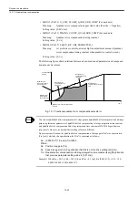
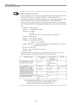
14.2.9 Model following control
To use model following control for positioning, set the following machine data and parame-
ters.
When model following control is enabled with the following machine data and parameters,
each of the parameters becomes always active for positioning (during RAPID, JOG, and pro-
grammed operation excluding handle feed or step feed operation.) (For cutting feed, rigid
tapping, and handle or step feed operation, the model following control becomes inactive.)
For procedures how to adjust model following control, refer to a separate manual.
If you want to use predictive control for positioning, disable model following control.
IMPORTANT
Summary of Contents for CNC Series
Page 1: ...Maintenance Manual Serviceman Handbook MANUAL No NCSIE SP02 19 Yaskawa Siemens CNC Series...
Page 26: ...Part 1 Hardware...
Page 38: ...System Configuration 1 2 3 Spindle motor designations 1 12...
Page 58: ...Installing the control panels 2 3 5 Installing lightning surge absorbers 2 20...
Page 62: ...Installing the motors 3 4...
Page 84: ...Connection method 4 3 2 Setting the rotary switches on the inverters and servo units 4 22...
Page 96: ...Part 2 Software...
Page 102: ...Software configuration 6 6...
Page 113: ...7 2 Network settings 7 11 8 Click on the radio button to the left of Specify an IP address...
Page 121: ...7 2 Network settings 7 19...
Page 122: ...Part 3 PLC...
Page 154: ...Part 4 Setting up and maintenance...
Page 160: ...Overview of System 10 1 2 Basic operation 10 6...
Page 204: ...How to use Digital Operation 12 2 9 Setting the password setting for write prohibit 12 32...
Page 327: ...Error and Troubleshooting 15 4...
Page 328: ...15 1 Errors without Alarm Display and Troubleshooting 15 5...
Page 329: ...Error and Troubleshooting 15 6...
Page 343: ...Maintenance and Check 16 3 3 Setting up Initializing Absolute encoder 16 14...


