


14.3 Motion Control
14-95
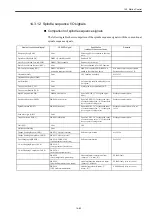
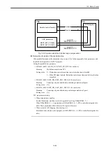
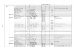
• MD21310 COUPLING_MODE_1
Meaning:
Spindle synchronicity mode
Setting value: 0---actual value coupling: Slave axis synchronizes with the master axis
position feedback value
1---setpoint coupling: The salve axis synchronizes with the master axis
position reference value.
2---speed coupling: Speed synchronization control
(normally not used since the position control is not executed in this
mode)
• MD21320 COUPLING_BLOCK_CHANGE_CTRL_1
Meaning:
Block changing mode during synchronicity
Setting value: 0---immediately change
1---change when ’Fine synchronism’ tolerance MD37210 is initiated
2---change when ’coarse synchronism’ tolerance MD37200 is initiated
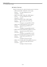
• MD21330 COUPLING_RESET_MODE_1
Meaning:
Synchronicity setting when rest
• MD21340 COUPLING_IS_WRITE_PROT_1
Meaning:
Synchronicity conditions modifying setting
Setting value: 0---adjustable with CNC program
1---not adjustable with CNC program
• MD37200 COUPLE_POS_TOL_COARSE
Meaning:
’Coarse synchronism’ tolerance range
Setting value: [mm] or [deg]
• MD37210 COUPLE_POS_TOL_FINE
Meaning:
’Fine synchronism’ tolerance range
Setting value: [mm] or [deg]
• SD42300 COUPLE_RATIO [0]
Meaning:
Numerator for synchronicity speed ratio
• MD42300 COUPLE_RATIO [1]
Meaning:
Denominator for synchronicity speed ratio
Setting value: Sets synchronicity speed ratio for spindle/following axis synchronizing
with spindle
Speed ratio = SD42300[0]/SD42300[1]
Settable with CNC program.
Summary of Contents for CNC Series
Page 1: ...Maintenance Manual Serviceman Handbook MANUAL No NCSIE SP02 19 Yaskawa Siemens CNC Series...
Page 26: ...Part 1 Hardware...
Page 38: ...System Configuration 1 2 3 Spindle motor designations 1 12...
Page 58: ...Installing the control panels 2 3 5 Installing lightning surge absorbers 2 20...
Page 62: ...Installing the motors 3 4...
Page 84: ...Connection method 4 3 2 Setting the rotary switches on the inverters and servo units 4 22...
Page 96: ...Part 2 Software...
Page 102: ...Software configuration 6 6...
Page 113: ...7 2 Network settings 7 11 8 Click on the radio button to the left of Specify an IP address...
Page 121: ...7 2 Network settings 7 19...
Page 122: ...Part 3 PLC...
Page 154: ...Part 4 Setting up and maintenance...
Page 160: ...Overview of System 10 1 2 Basic operation 10 6...
Page 204: ...How to use Digital Operation 12 2 9 Setting the password setting for write prohibit 12 32...
Page 327: ...Error and Troubleshooting 15 4...
Page 328: ...15 1 Errors without Alarm Display and Troubleshooting 15 5...
Page 329: ...Error and Troubleshooting 15 6...
Page 343: ...Maintenance and Check 16 3 3 Setting up Initializing Absolute encoder 16 14...


