


14-
112
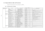
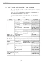
14.6 Trouble shooting
14.6.1 Table of causes/countermeasures for troubles
Following list is the summary of causes and countermeasures for potential troubles occurring from the setting errors of machine data or parameters.
。
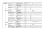
Category
Symptom
Conditions
Candidate causes
Measures
Remarks
(relevant sections)
Controlled
source
There is one or more axis which can not be read by the digital operator of converter.
Or There occurs the drive alarm 183 (A. B7: Link setting error) or 225 (A. E1: Tim-
eout error).
When the control source is powered on.
There may exist any mismatchings on the axis number rotary switch of the drive.
Check if there are multiple switches specified for the same number under a single con-
verter.
Check if the switch setting is within the range between 0 and 6.
Check if the switch indicates the target number properly.
14.1.4
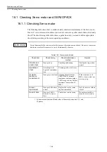
When powered on, the position becomes approximately fourfold the setting value.
When the control source is powered on.
The multiplication factor for the absolute value data is incorrectly set.
Set the value, MD 30260 = 1.
14.1.5
There occurs the drive alarm 4 (A.0.4: Parameter setting is abnormal).
When the control source is powered on.
The parameter setting value is out of the setting range.
Set the parameter value within the setting range.
A.1, A2
There occurs the drive alarm 2 (A.02: Flash memory is abnormal).
When the control source is powered on.
The checksum for user parameter or system parameter is abnormal.
Parameter ID check is abnormal.
Re-enter the parameter file for drive.
There occurs CNC alarm 8044.
When CNC power supply is powered on.
Limitation for IPO cycle is not released.
Set the value, MD19296 = 4.
14.1.1
There occurs CNC alarm 1019 Floating point arithmetic error.
When the control source is powered on.
The value MD32250[0] = 0 is set.
Set the value MD32250[0] = 100.
14.1.7
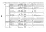
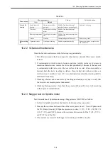
Servo drive is
powered on
The feed axis behaves inching when the servo drive is powered on.
When restarting after an emergency stop.
The variable Kp setting is not enabled on the drive side.
Set the value MD3069 digit 0 (Pn127 digit 0) = 0.
14.2.1
Including an axis with enabled separately mounted
encoder.
MD32642 is set to 1 for the axis with disabled separately mounted encoder.
Set 0 to MD32642 for the axis with disabled separately mounted encoder.
14.1.6
The feed axis coasts after the servo drive is powered on.
Especially the gravity axis
There is some mismatching between MD30110 and MD30220[0] or [1].
Specify the same value for MD30110 and MD30220[0] or [1].
14.1.5
There appears one or more runaway axes, when the servo drive is powered on.
In PLC, the measuring system (DB3nDBX1.5-6) is incorrectly selected.
Specify "1" for motor encoder only, and "2" for including separately mounted encoder.
14.1.5,14.1.6
Including the separately mounted encoder
The direction of motor rotation is unmatched to that of encoder rotation.
Correct the rotation directions.
14.1.6
The setting for separately mounted encoder is unmatched for CNC and the drive.
Specify the correct value.
14.1.6
Move command does not match the actual travel amount .
Including the separately mounted encoder.
The setting value for the separately mounted encoder is incorrect.
Correctly set the values for both the motor encoder and the separately mounted encoder.
14.1.5,14.1.6
There occurs CNC alarm 1019 Floating point arithmetic error.
In 00.02.02 system, when the servo drive is powered on. MD32642 is set to 1 for the semi-closed controlled (motor encoder controlled) axis.
Set 0 to MD32642 for the semi-closed controlled axis.
14.1.6
Vibration
When the servo drive is powered on.
The unit for setting value for Kp is incorrect.
Use the same unit for MD102390[9] and MD32200.
14.2.1
There occurs the drive alarm 81 (A.51: Undervoltage).
Multiple converters are connected.
Before the servo drive under one converter is powered off, another converter has
blocked the main circuit connector.
With MC3528(Pn81C) and MD6989(Cn8C9), specify the amount for the delay time for
the axis for which the servo drive is last to be powered on (for example, longer than the
deceleration time for the spindle).
14.3.4
It is impossible to power on the servo drive.
Whole axes are disabled.
The bus cable connector linking with drives is almost disconnected.
Check the connection of bus cable connector linking with the drives.
A single axis is disabled.
In PLC, the measuring system (DB3nDBX1.5-6) is not selected.
Specify "1" for motor encoder only, and "2" for including separately mounted encoder.
14.1.6
Separately mounted encoder absolute value detection
function is enabled.
The motor encoder setting value is not set to the absolute value detection.
When the absolute value detection function is enabled on the separately mounted encoder,
set the motor encoder type to the absolute value encoder (MD30340[0] = 4) independently
with the motor encoder type.
14.1.5
When servo drive is powered on, or when the first travel command is instructed,
there occurs a servo drive alarm 113 (A.71: Overloading).
Including separately mounted encoder.
The direction setting for the separately mounted encoder is incorrect.
Check the orientation of separately mounted encoder and correct the relevant machine data
and parameters.
14.1.6
There occurs a servo drive alarm 113 (A.71: Overloading).
When the servo drive is powered on.
The motor cable is disconnected.
Connect the motor cable properly.
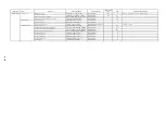
Control
Torque fluctuates in wave forms during deactivation.
Including separately mounted encoder.
The separately mounted encoder is set to Type 1 (MD32642 = 0).
Set the encoder to Type 2 (MD32642 = 1).
Standard setting is
Type 2.
14.1.6
There occurs CNC alarm 21610 Channel ** axis** encoder frequency exceeded.
Including separately mounted encoder.
Since the setting value with MD30600[1] is not high enough, the command frequency
is abnormal.
Set the setting value with MD30600[1] to equal or higher value than 4 or the separately
mounted encoder pulse rate (pps) at the top speed.
14.1.6
There occurs the drive alarm 208 (A. D0 Position deviation is excessive).
During the rapid travelling.
The setting value for excessive deviation range on the drive side is not high enough.
Specify the value appropriate for the encoder and Kp with MD3425 (Pn505).
14.2.1
Emergency stop is not initiated but DB stop (spindle is free-running) is enabled.
-
The delay time between the emergency stop and the servo drive cut-off is too short.
With MD3442 (Pn516) and/or MD6511 (Cn511), specify the proper value (for example,
the value which is equal or exceed the spindle deceleration time) for the time from the
emergency stop until the servo drive is cutoff.
14.3.4
The position deviation is not match Kp.
Including separately mounted encoder.
The separately mounted encoder reverse connection is installed on the CNC side in
case of the separately mounted encoder reverse connection along with the motor for-
ward connection.
In this case, the separately mounted encoder reverse connection should be done on the
drive side.
14.1.6
There occurs low frequency vibration (about 20 Hz) during deactivation.
Quadrant jerk compensation is enabled.
The setting value for the functional quadrant jerk compensation function selection is
wrong (current setting may be MD3068 digit 1 (Pn126 digit 1) = 1).
Correct the setting with MD3068 digit 1 (Pn126 digit 1) = 2.
14.2.5
Summary of Contents for CNC Series
Page 1: ...Maintenance Manual Serviceman Handbook MANUAL No NCSIE SP02 19 Yaskawa Siemens CNC Series...
Page 26: ...Part 1 Hardware...
Page 38: ...System Configuration 1 2 3 Spindle motor designations 1 12...
Page 58: ...Installing the control panels 2 3 5 Installing lightning surge absorbers 2 20...
Page 62: ...Installing the motors 3 4...
Page 84: ...Connection method 4 3 2 Setting the rotary switches on the inverters and servo units 4 22...
Page 96: ...Part 2 Software...
Page 102: ...Software configuration 6 6...
Page 113: ...7 2 Network settings 7 11 8 Click on the radio button to the left of Specify an IP address...
Page 121: ...7 2 Network settings 7 19...
Page 122: ...Part 3 PLC...
Page 154: ...Part 4 Setting up and maintenance...
Page 160: ...Overview of System 10 1 2 Basic operation 10 6...
Page 204: ...How to use Digital Operation 12 2 9 Setting the password setting for write prohibit 12 32...
Page 327: ...Error and Troubleshooting 15 4...
Page 328: ...15 1 Errors without Alarm Display and Troubleshooting 15 5...
Page 329: ...Error and Troubleshooting 15 6...
Page 343: ...Maintenance and Check 16 3 3 Setting up Initializing Absolute encoder 16 14...


