


Chapter 7 - System Description
_______________________________________________________________________________________________________________
MNL000301.doc
Revision 2
01/04/2019
SourceSystem TE11
© Versum Materials, Inc. as of the revision and date shown. All rights reserved.
Confidential and Proprietary Data
Page
7
-
23
If the actual pressure decay was less than the preset limit, the system has passed. Post purge can now
be initiated (refer to appropriate section in operation manual). If the pressure decay was equal to or
greater than the limit, the test will abort and the system will alarm indicating that the test has failed.
The connection must be remade and the cylinder change sequence performed again. Note, prior to re-
running the cylinder change sequence, the operator must ensure a vacuum condition at PT1 and PT2.
If not at a vacuum, the operator must manually achieve vacuum at PT1 and PT2 before change cylinder
mode can be started. If the HPLT fails, the controller will not allow post purge and process gas
sequences to start. HPLT must be successfully completed before any further operations are permitted.
EFS1
V44
EFS1
V11
CV11
CV9
V10
MV22
MV22
CV3
CV3
CV2
CV2
CV7
MV9
MV9
TRICKLE PURGE
ORIFICE
PT1
PT2
PT1
PT2
PT5
PCV
1
PCV
1
V2
V2
V3
V3
V4
V4
V5
V6
V5
V6
V7
PT8
VENT
VENTURI
SUPPLY
PROCESS
OUT
LOW
PRESSURE
PURGE
HIGH
PRESSURE
PURGE
PROCESS
PROCESS
RESTRICTIVE
FLOW
ORIFICE
V0
V0
MV4
MV4
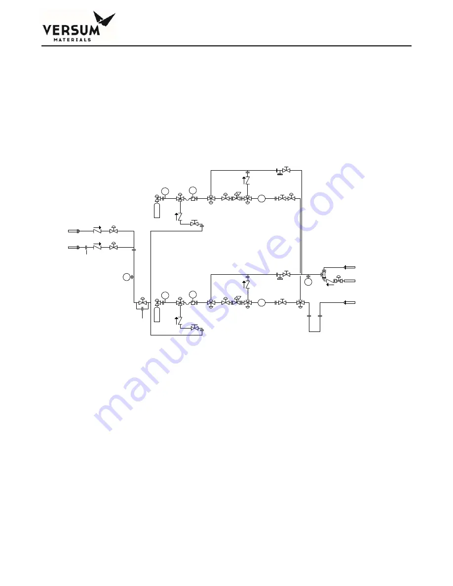
Figure 7.8:
Example HPLT Piping Schematic


