


Cable and Antenna Test Mode
R&S
®
Cable Rider ZPH
127
User Manual 1321.0950.02 ─ 03
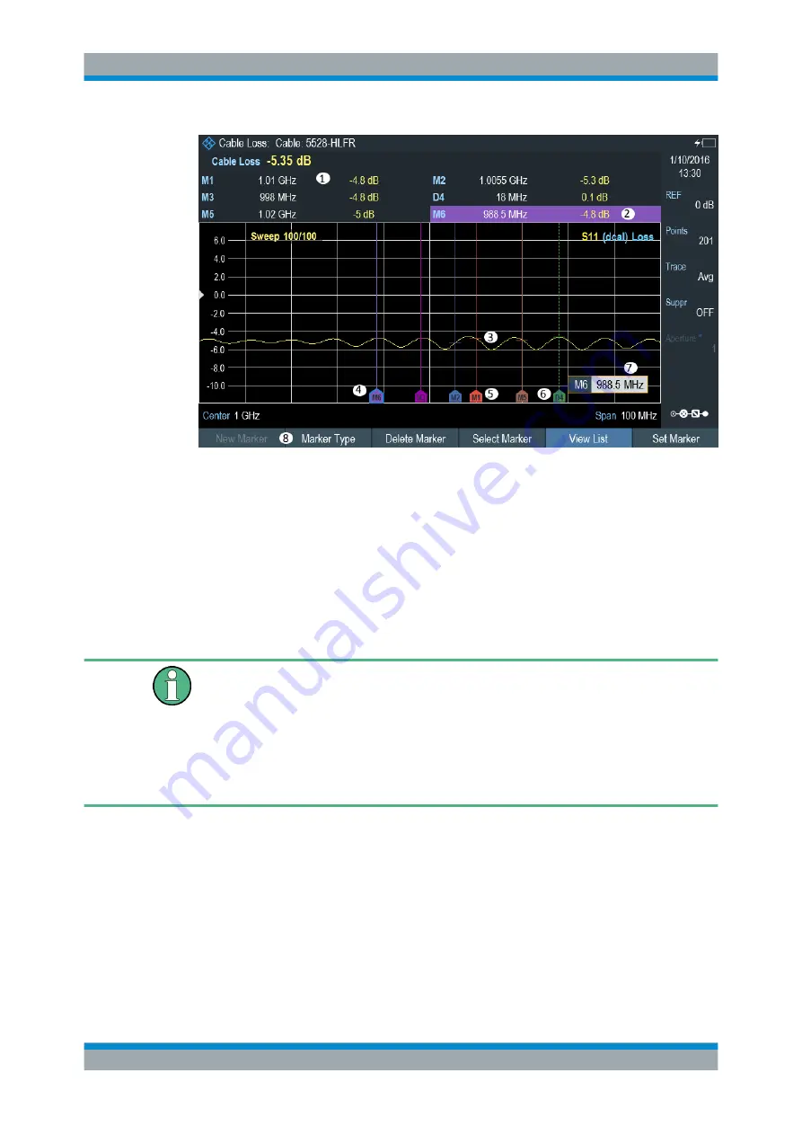
Figure 7-10: Screen layout with active markers
1 =
2 = Marker (solid line)
3 = Delta marker (dotted line)
4 = Active marker label (see highlighted line on the marker list as well as the marker label )
5 = Marker label: M(x)
6 = Delta marker label: D(x)
7 = Marker input field
8 = Marker menu
Positioning Markers
Special touchscreen gesture
Double tap on the touchscreen to position new marker on the trace window. The first
marker that is positioned on the trace window is always the main marker, the following
markers added on the trace window are the delta markers.
Tab and drag on the marker icon to change the marker position.
See
1. Press the MARKER key.
If, as yet, no marker has been activated, the R&S Cable Rider ZPH automatically
activates the main marker and positions it on the maximum level that has been
measured. In addition, the marker frequency input field opens.
You can perform the following actions:
● Tab and drag on the marker icon to change the marker position.
● Position the marker with the rotary knob
When positioning the marker with the rotary knob, the step size is one pixel.
Analyzing Measurement Results


