


44
External I/O Circuits
Section 3-3
■
Output Signal Assignment Details
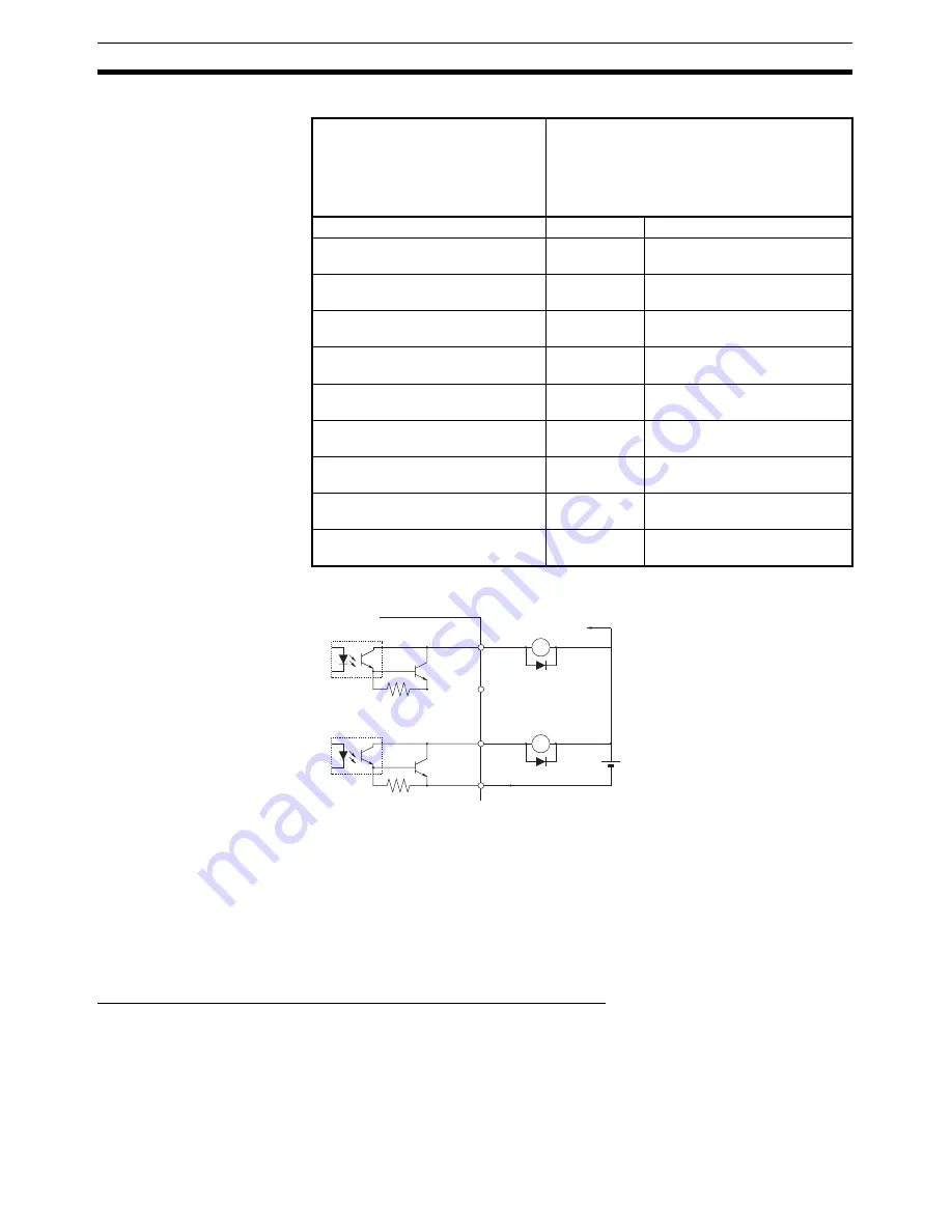
Control Output Circuits
3-3-3
W-series Servo Drive I/O Signals (R88D-WT
@
with JUSP-NS115)
This section explains the I/O signals used between the PCU and a W-series
Servo Drive equipped with a JUSP-NS115 MECHATROLINK-II Application
Module.
Use the
OMNUC W Series User's Manual
together with this manual for infor-
mation on I/O signals.
Terminal Arrangement of the Control I/O Connector (CN1)
The following diagram shows the terminal arrangement of the W-series Servo
Drive's Control I/O Connector (CN1) when MECHATROLINK is being used
with the Servo Drive's standard settings.
This diagram shows only the I/O signals used when connecting to the PCU.
For details on the Servo Drive's standard settings, refer to
6-4 Standard Set-
tings for Servo Drives Using MECHATROLINK
.
Pn112 (General-purpose Output 1
Function Selection)
Pn113 (General-purpose Output 2
Function Selection)
Pn114 (General-purpose Output 3
Function Selection)
OUTM1 (General-purpose Output 1)
OUTM2 (General-purpose Output 2)
OUTM3 (General-purpose Output 3)
0
Not assigned
No output. Always OFF.
1
INP1
Positioning Completed 1 output
assignment.
2
VCMP
Speed Conformity Signal out-
put assignment.
3
TGON
Servomotor Rotation Speed
Detection output assignment.
4
READY
Servo Ready output assign-
ment.
5
CLIM
Current Limit Detection output
assignment.
6
VLIM
Speed Limit Detection output
assignment.
7
BKIR
Brake Interlock output assign-
ment.
8
WARN
Warning Signal output assign-
ment.
9
INP2
Positioning Completed 2 output
assignment.
Servo Drive
To other output
circuits
External power supply
24 VDC
±
1 V
Maximum operating voltage: 30 VDC
Maximum output current: 50 mA
Di: Diode for preventing surge voltage
(Use high-speed diodes.)
X
Di
X
Di
+
+
−
−
Summary of Contents for CJ1W-MA - REV 10-2008
Page 3: ...iv ...
Page 5: ...vi ...
Page 21: ...xxii ...
Page 57: ...30 Starting Operation Section 2 2 ...
Page 97: ...70 Wiring Section 3 4 ...
Page 247: ...220 Transferring Servo Parameters Section 5 3 ...
Page 281: ...254 Standard Settings for Servo Drives Using MECHATROLINK Section 6 4 ...
Page 343: ...316 Absolute Encoder Origin Section 8 6 ...
Page 375: ...348 Linear Interpolation Section 9 7 ...
Page 423: ...396 DEVIATION COUNTER RESET Section 10 10 ...
Page 631: ...604 Additional Functions for the CJ1W NCF71 MA Appendix F ...
Page 641: ...614 Index ...
Page 643: ...616 Revision History ...


