


310
Absolute Encoder Origin
Section 8-6
b = Beginning word of Axis Operating Input Areas specified in Common
Para (Axis No.
−
1)
×
25
8-6-4
Absolute Encoder Setup
The absolute encoder setup must be performed when using the absolute
encoder for the first time, initializing the rotation amount to 0, or having left the
absolute encoder for a long time without connecting a battery.
The following methods can be used to set up the absolute encoder when
using a Position Control Unit with unit version 1.2 or later.
• The absolute encoder can be set up using the CX-Motion-NCF.
• The absolute encoder can be set up from the user program using a func-
tion block from the OMRON FB Library.
• The absolute encoder can be set up using the Servo Drive's Setting Tool.
Refer to the
SYSMAC CX-Motion-NCF Programmable Controller Operation
Manual
(Cat. No. W436) for information on setting up the absolute encoder
from the CX-Motion-NCF.
When setting up an absolute encoder using the function block from the
OMRON FB Library, use a CPU Unit with unit version 3.0 or later.
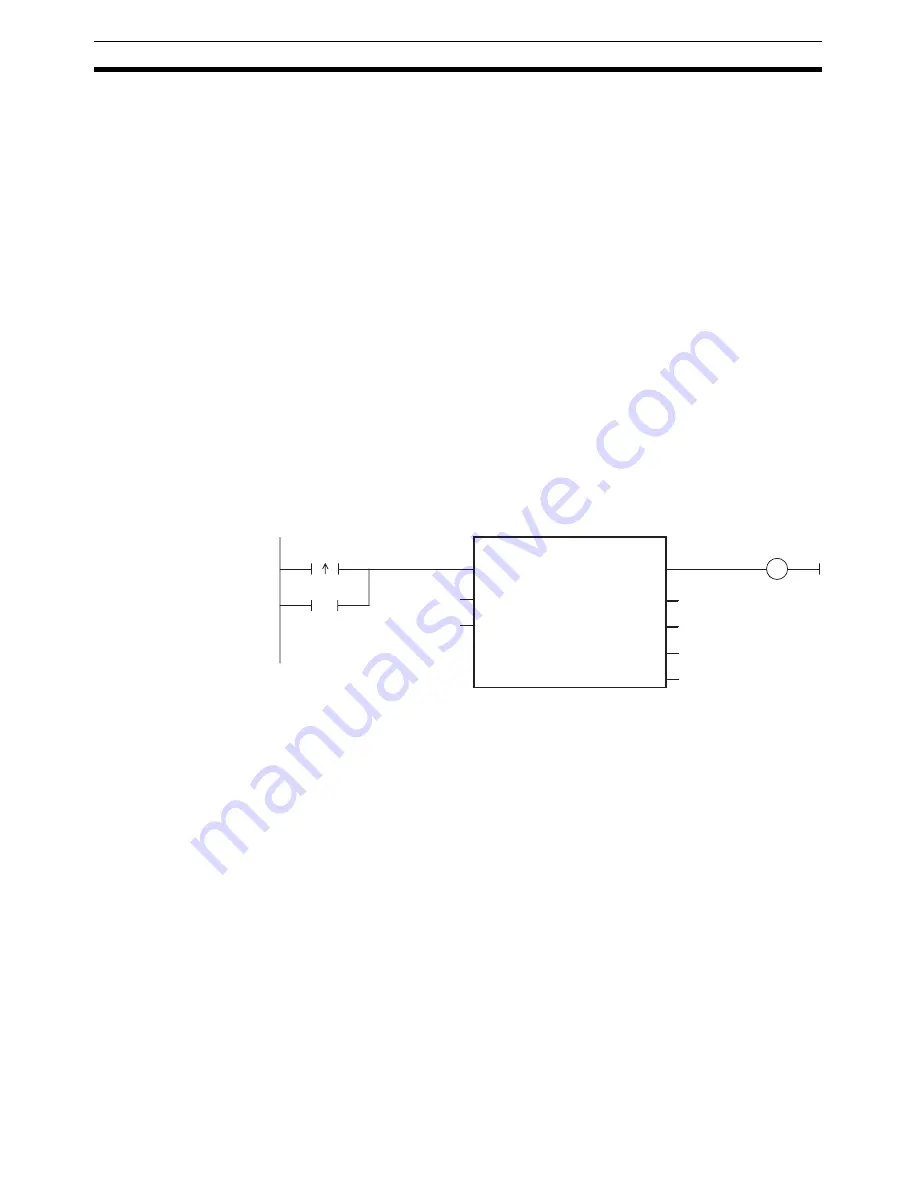
Absolute Encoder Setup Function Block in OMRON FB Library:
_NCF700_InitializeAbsEncoder
The absolute encoder setup can be executed by specifying the unit number
and axis number for the function block, and setting the Start Bit.
For information on function block operating requirements and precautions,
refer to the
OMRON FB Library Reference Manual
(Cat. No. W442).
When using a PCU with unit version 1.1 or earlier, absolute encoder setup is
executed using the Servo Drive’s Setting Tool. For details on absolute
encoder setup operations using the Servo Drive Setting Tool, refer to the
operation manual for the connected Servo Drive.
Note
After executing absolute encoder setup, be sure to turn ON the Servo Drive’s
control power supply again. Not doing so will prevent the Servo Drive’s
response to PCU commands, and normal operation will not be possible.
8-6-5
Absolute Encoder's Origin (Zero Point) Position Offset Setting
When Absolute Origin Offset for G Series (Pn200) or Absolute Encoder Zero Point Position Offset for
W Series (Pn808) = 0 (Default)
1,2,3...
1.
Start MECHATROLINK communications (establish a connection using
CONNECT).
2.
Use jogging or other operation to place the machine in the mechanical or-
igin position. ORIGIN SEARCH cannot be used when using an absolute
encoder.
Unit No.
Axis No.
Busy Flag
Setup completed
Error Flag
Error Code
(Can be omitted)
Start Bit
Busy Flag
_NCF700_InitializeAbsEncoder
(BOOL)
EN
(BOOL)
ENO
(INT)
UnitNo
(BOOL)
Busy
(INT)
Axis
(BOOL)
Done
(BOOL)
Error
(WORD)
ErrorID
Summary of Contents for CJ1W-MA - REV 10-2008
Page 3: ...iv ...
Page 5: ...vi ...
Page 21: ...xxii ...
Page 57: ...30 Starting Operation Section 2 2 ...
Page 97: ...70 Wiring Section 3 4 ...
Page 247: ...220 Transferring Servo Parameters Section 5 3 ...
Page 281: ...254 Standard Settings for Servo Drives Using MECHATROLINK Section 6 4 ...
Page 343: ...316 Absolute Encoder Origin Section 8 6 ...
Page 375: ...348 Linear Interpolation Section 9 7 ...
Page 423: ...396 DEVIATION COUNTER RESET Section 10 10 ...
Page 631: ...604 Additional Functions for the CJ1W NCF71 MA Appendix F ...
Page 641: ...614 Index ...
Page 643: ...616 Revision History ...


