


382
Backlash Compensation
Section 10-7
• After Backlash Compensation
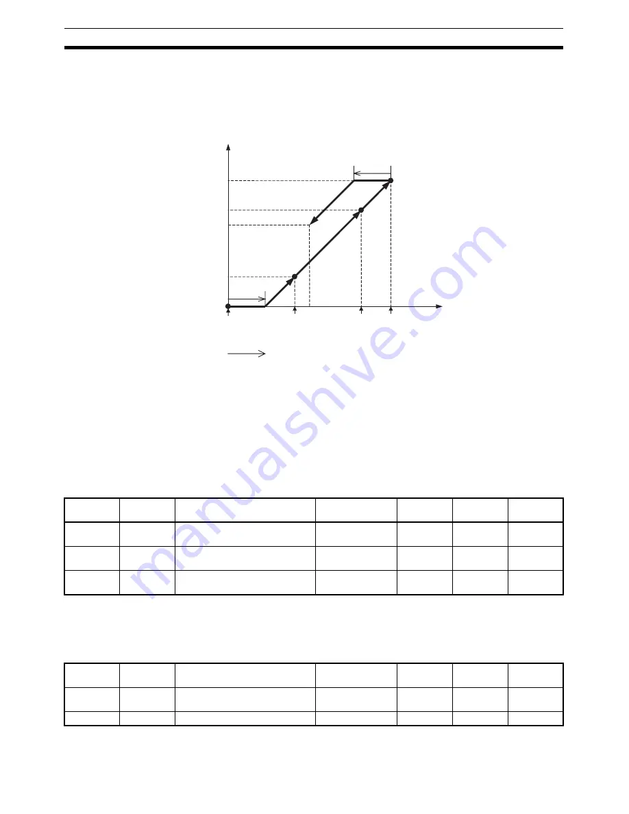
Backlash compensation is applied for the first operating command that
operates in the opposite direction from which backlash compensation was
previously applied. Once backlash compensation has been applied, it will
not be applied again as long as operation is continued in the same direc-
tion.
Note
The PCU's present position compensation according to the backlash compen-
sation function is applied to both the feedback present position and command
present position.
10-7-3 Backlash Compensation Data Settings
When a G-series Servo Drive or a W-series Servo Drive is connected, the
data settings for backlash compensation are as follows:
Servo Parameter Area
Backlash Compensation Parameters (R88D-GN
@
-ML2)
The backlash compensation amount is set in Pn101 in command units. The
minimum setting unit for the backlash compensation amount, however,
depends on the encoder resolution.
Backlash Compensation Parameters (R88D-WT
@
+ JUSP-NS115)
Present position managed by PCU
Compensation amount
(4)
(3)
(1)
(2)
Compen-
sation
amount
Start (1)
(First time after
SERVO LOCK)
Start (2)
Start (4)
Start (3)
Specified backlash compensation direction
Number of Servomotor rotations
Type
Parameter
No.
Parameter name
Unit
Setting
range
Data
length
Default
setting
---
Pn100
Backlash compensation selec-
tion
---
0 to 2
2
0
---
Pn101
Backlash compensation
Command unit
−
32,768 to
32,767
2
0
---
Pn102
Backlash compensation time
constant
0.01ms
0 to 6400
2
0
Type
Parameter
No.
Parameter name
Unit
Setting
range
Data
length
Default
setting
---
Pn81B
Backlash compensation amount
0.1 command unit
−
32,768 to
32,767
2
0
---
Pn81D.0
Compensation function selection ---
0, 1
2
0
Summary of Contents for CJ1W-MA - REV 10-2008
Page 3: ...iv ...
Page 5: ...vi ...
Page 21: ...xxii ...
Page 57: ...30 Starting Operation Section 2 2 ...
Page 97: ...70 Wiring Section 3 4 ...
Page 247: ...220 Transferring Servo Parameters Section 5 3 ...
Page 281: ...254 Standard Settings for Servo Drives Using MECHATROLINK Section 6 4 ...
Page 343: ...316 Absolute Encoder Origin Section 8 6 ...
Page 375: ...348 Linear Interpolation Section 9 7 ...
Page 423: ...396 DEVIATION COUNTER RESET Section 10 10 ...
Page 631: ...604 Additional Functions for the CJ1W NCF71 MA Appendix F ...
Page 641: ...614 Index ...
Page 643: ...616 Revision History ...


