


493
Performance Characteristics
Appendix A
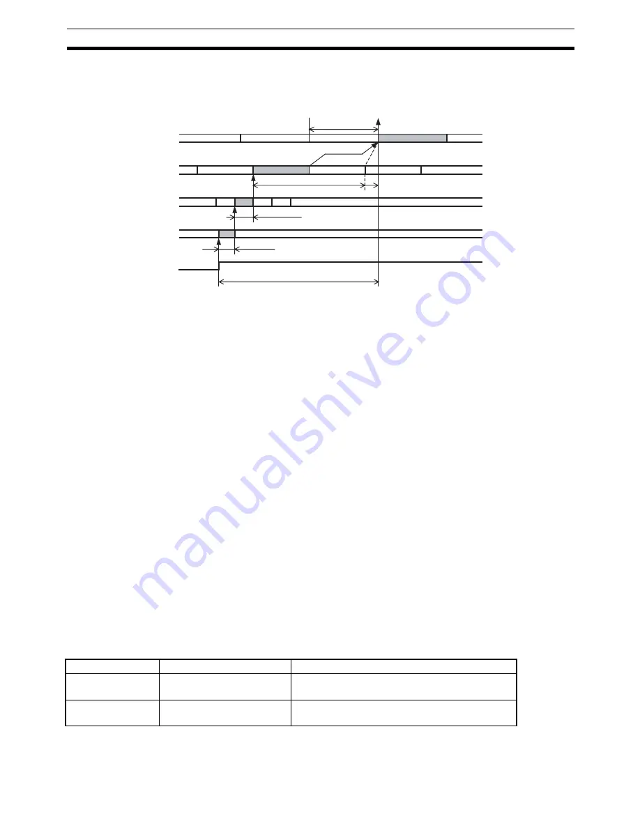
Response Time to Reflect Servo Drive Status Changes in CPU Unit
The response time starts when status transmitted via MECHATROLINK communications is sampled and con-
tinues until that status is refreshed in the CPU Unit's input status.
The processing time for the changes in status detected in the Servo Drive to be sent using MECHATROLINK
communications is indicated as T
SRV_IN
:
250
µ
s + transfer cycle (using R88D-GN
@
-ML2)
625
µ
s (using an R88D-WT
@
and JUSP-NS115 MECHATROLINK-II Application Module or the SMART-
STEP Junior)
450
µ
s (using an R88D-WN
@
-ML2)
The time for the Servo Drive status to reach the PCU via MECHATROLINK communications is indicated as
T
MLK
:
MECHATROLINK transfer cycle
×
1
The maximum time from the end refresh of the user program's cycle in which the command was sent until the
command is actually received by the PCU is T
IN_REF
:
(CPU cycle time or MECHATROLINK communications cycle, whichever is longer) + CPU Unit's cycle time
×
1
The maximum value for the time until changes in the Servo Drive status are reflected in the CPU Unit's user
program, as indicated by T
RES
, is a total of these values, as follows:
T
RES(MAX)
= T
SRV_IN
+ T
MLK
+ T
IN_REF
Note
T
RES
varies depending on the width of T
IN_REF
.
Example:
CPU Unit cycle time:
1 ms
PCU communications setting: Transfer cycle: 1 ms
Communications cycle = 1 (transfer cycle
×
1 = 1 ms)
Connected Servo Drive:
W-series Servo Drive + JUSP-NS115
The command response time for the above conditions is as follows:
(This example applies when no warning has occurred in the PCU.)
Note
When mounting a Position Control Unit to a CS-series Long-distance Expansion Rack, refer to the graph
on I/O refresh time coefficients in the
CS-series CPU Unit Operation Manual
(Cat. No. W339).
CPU Unit cycle time
PCU processing
Servo Drive processing
T
MLK
=
Transfer cycle
T
SRV_IN
Reflected in ladder program
T
IN_REF
T
RES
Cycle time
NC
→
CPU
MECHATROLINK
communications
cycle
Servo Drive status
change sampling
(e.g., changing status)
Item
Maximum response time
Calculation method
CPU Unit to PCU
4.625 ms
T
CMD(MAX)
= T
OUT_REF
+ T
NC
+ T
MLK
+ T
SRV_OUT
= 2 ms + 1 ms + 1 ms +625
µ
s
PCU to CPU Unit
3.625 ms
T
RES(MAX)
= T
SRV_IN
+ T
MLK
+ T
IN_REF
= 625
µ
s + 1 ms + 2 ms
Summary of Contents for CJ1W-MA - REV 10-2008
Page 3: ...iv ...
Page 5: ...vi ...
Page 21: ...xxii ...
Page 57: ...30 Starting Operation Section 2 2 ...
Page 97: ...70 Wiring Section 3 4 ...
Page 247: ...220 Transferring Servo Parameters Section 5 3 ...
Page 281: ...254 Standard Settings for Servo Drives Using MECHATROLINK Section 6 4 ...
Page 343: ...316 Absolute Encoder Origin Section 8 6 ...
Page 375: ...348 Linear Interpolation Section 9 7 ...
Page 423: ...396 DEVIATION COUNTER RESET Section 10 10 ...
Page 631: ...604 Additional Functions for the CJ1W NCF71 MA Appendix F ...
Page 641: ...614 Index ...
Page 643: ...616 Revision History ...


