


503
List of Parameters
Appendix B
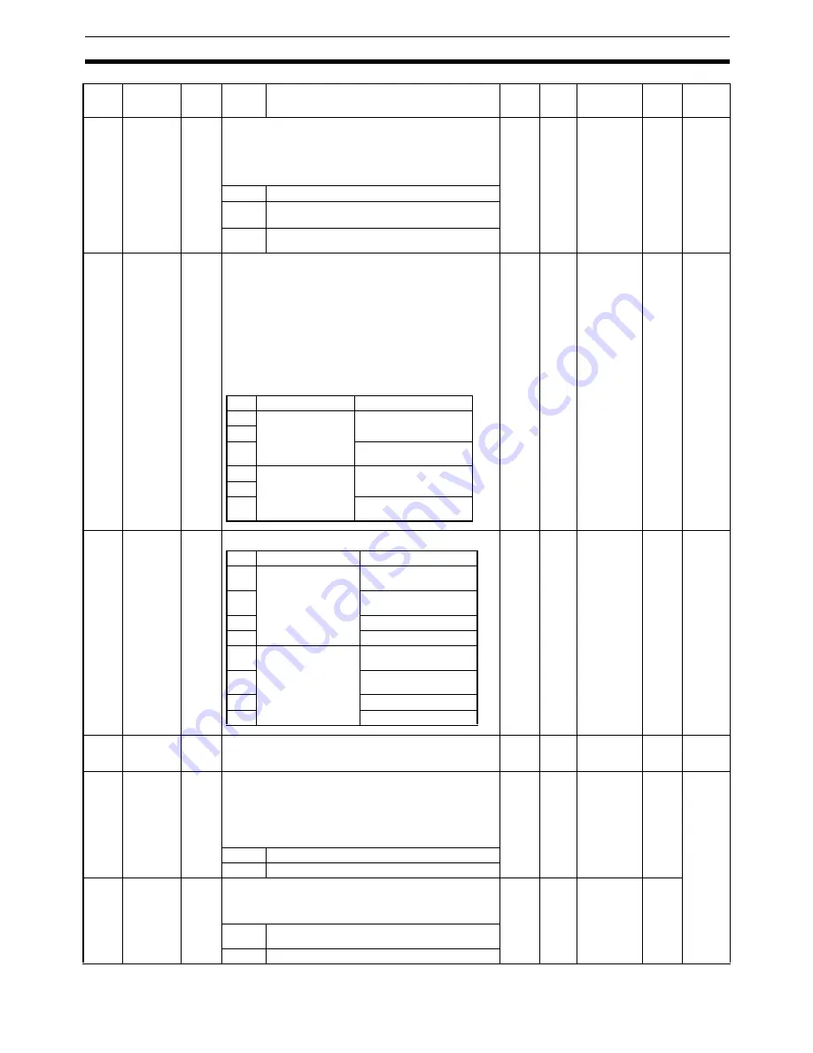
Pn023
Adaptive
Filter Selec-
tion
2
Enables or disables the adaptive filter.
The Adaptive Filter Table Number Display (Pn02F) will be reset to
0 when disabled.
Note
When the Vibration Filter Selection (Pn024) is set to a
low-pass filter type (Pn024 = 3 to 5), the adaptive filter is
forcibly set to disabled (Pn023 = 0).
0
---
0 to 2
Online
Settings
can be
changed
when the
axes are
stopped
(Busy
Flag for
each axis
= 0).
0
Adaptive filter disabled.
1
Adaptive filter enabled.
Adaptive operation performed.
2
Adaptive filter enabled. Adaptive operation will not be
performed (i.e., retained).
Pn024
Vibration
Filter Selec-
tion
2
Selects the vibration filter type and switching mode.
• Filter type selection
• Normal type:
Vibration frequency setting range 10.0 to 200.0 Hz
• Low-pass type:
Vibration frequency setting range 1.0 to 200.0 Hz
• Switching mode selection
• No switching: Both 1 and 2 are enabled
• Switching with command direction:
Selects Vibration Frequency 1 in forward direction
(Pn02B, Pn02C)
Selects Vibration Frequency 2 in reverse direction
(Pn02D, Pn02E)
0
---
0 to 5
Offline
Pn025
Normal
Mode Auto-
tuning
Operation
Setting
2
Sets the operating pattern for normal mode autotuning.
0
---
0 to 7
Online
Settings
can be
changed
when the
axes are
stopped
(Busy
Flag for
each axis
= 0).
Pn026
Overrun
Limit Set-
ting
2
Sets the Servomotor’s allowable operating range for the position
command input range.
Set to 0 to disable the overrun protective function.
10
×
0.1
rota-
tion
0 to 1000
Online
Pn027
Instanta-
neous
Speed
Observer
Setting (RT)
2
The Instantaneous Speed Observer improves speed detection
accuracy, thereby improving responsiveness and reducing vibra-
tion when stopping.
When the instantaneous speed observer is enabled, both Speed
Feedback Filter Time Constant (Pn013) and Speed Feedback Fil-
ter Time Constant 2 (Pn01B) are disabled.
This feature cannot be used with realtime autotuning.
0
---
0, 1
Online
Settings
can be
changed
when the
axes are
stopped
(Busy
Flag for
each axis
= 0).
0
Disabled
1
Enabled
Pn028
Notch Filter
2 Fre-
quency
2
Sets the notch frequency of notch filter 2 for resonance suppres-
sion.
This parameter must be matched with the resonance frequency of
the load.
1500
Hz
100 to 1500
Online
100 to
1499
Filter enabled
1500
Filter disabled
Param-
eter
No.
Parameter
name
Param-
eter
size
Setting
Explanation
Default
setting
Unit
Setting
range
Enable
setting
Details
Filter type
Switching mode
0
Normal type
No switching
1
2
Switching with command
direction
3
Low-pass type
No switching
4
5
Switching with command
direction
Number of rotations
Rotation direction
0
Repeat cycles of 2
rotations
Forward and Reverse
(Alternating)
1
Reverse and Forward
(Alternating)
2
Forward only
3
Reverse only
4
Repeat cycles of single
rotation
Forward and Reverse
(Alternating)
5
Reverse and Forward
(Alternating)
6
Forward only
7
Reverse only
Summary of Contents for CJ1W-MA - REV 10-2008
Page 3: ...iv ...
Page 5: ...vi ...
Page 21: ...xxii ...
Page 57: ...30 Starting Operation Section 2 2 ...
Page 97: ...70 Wiring Section 3 4 ...
Page 247: ...220 Transferring Servo Parameters Section 5 3 ...
Page 281: ...254 Standard Settings for Servo Drives Using MECHATROLINK Section 6 4 ...
Page 343: ...316 Absolute Encoder Origin Section 8 6 ...
Page 375: ...348 Linear Interpolation Section 9 7 ...
Page 423: ...396 DEVIATION COUNTER RESET Section 10 10 ...
Page 631: ...604 Additional Functions for the CJ1W NCF71 MA Appendix F ...
Page 641: ...614 Index ...
Page 643: ...616 Revision History ...


