


332
Interrupt Feeding
Section 9-5
9-5-3
Data Settings for Using Interrupt Feeding
To execute interrupt feeding, the following parameters and data must be set in
addition to the parameters and data required for direct operation.
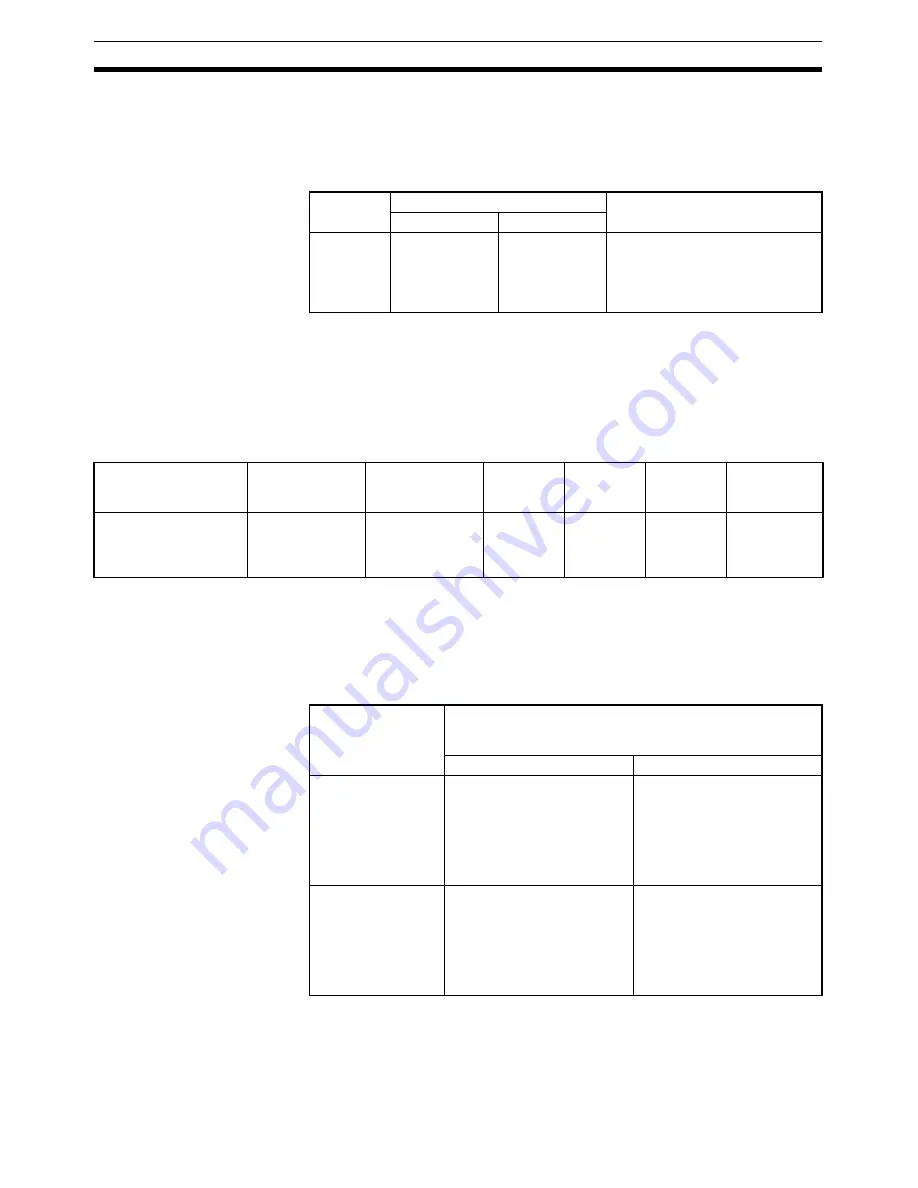
Axis Parameter Area
Interrupt Input Signal Parameters
d = 1860 hex + (Axis No.
−
1)
×
14 hex
When using external latch signals 1 to 3, the external latch signal to be used
must be allocated in the Servo Drive's external input allocations.
When using a SMARTSTEP Junior Servo Drive, only 00 (phase Z) and 01
(external latch signal 1) can be used for the origin input signal selection.
Servo Parameter Area
Interrupt Feeding Parameters
Set the travel distance from the position at which the interrupt input signal is
input. The travel direction for when the interrupt input signal is input is deter-
mined by the sign (positive or negative) in the set value. The operation per-
formed when the interrupt input signal is input depends on the sign for this
parameter and the sign of the position command value for direct operation, as
follows:
Note
When using a Position Control Unit with unit version 2.0 or later, the
Final Dis-
tance for External Input Positioning
for G-series Servo Drives (Pn203) or
Final
Travel Distance for External Positioning
for W-series Servo Drives (Pn814) is
used for internal processing in the Position Control Unit for either of the follow-
ing origin search operation patterns.
PCU's
address
Contents
Setting
Bits 08 to 15
Bits 00 to 07
d
Origin input sig-
nal selection
Interrupt input
signal selection
Interrupt input signal selection
00: Phase Z
01: External latch signal 1 input
02: External latch signal 2 input
03: External latch signal 3 input
Parameter name for G
Series (Parameter
name for W Series)
Unit
Setting range
Parameter
size
Default
setting
G Series
W Series and
SMARTSTEP
Junior Series
Final distance for exter-
nal input positioning
(Final travel distance for
external positioning)
Command unit
−
1,073,741,823 to
1,073,741,823
4
100
Pn203
Pn814
Position command
value for direct
operation
Final distance for external input positioning for G Series
(Pn203) or Final travel distance for external positioning
for W Series (Pn814)
Positive value
Negative value
Positive value
When the interrupt input sig-
nal is input, interrupt feeding
is executed in the same direc-
tion as the travel direction
when movement was started.
When the interrupt input sig-
nal is input, interrupt feeding
is executed in the opposite
direction from the travel direc-
tion when movement was
started.
(Reversal mode operation)
Negative value
When the interrupt input sig-
nal is input, interrupt feeding
is executed in the opposite
direction from the travel direc-
tion when movement was
started.
(Reversal mode operation)
When the interrupt input sig-
nal is input, interrupt feeding
is executed in the same direc-
tion as the travel direction
when movement was started.
Summary of Contents for CJ1W-MA - REV 10-2008
Page 3: ...iv ...
Page 5: ...vi ...
Page 21: ...xxii ...
Page 57: ...30 Starting Operation Section 2 2 ...
Page 97: ...70 Wiring Section 3 4 ...
Page 247: ...220 Transferring Servo Parameters Section 5 3 ...
Page 281: ...254 Standard Settings for Servo Drives Using MECHATROLINK Section 6 4 ...
Page 343: ...316 Absolute Encoder Origin Section 8 6 ...
Page 375: ...348 Linear Interpolation Section 9 7 ...
Page 423: ...396 DEVIATION COUNTER RESET Section 10 10 ...
Page 631: ...604 Additional Functions for the CJ1W NCF71 MA Appendix F ...
Page 641: ...614 Index ...
Page 643: ...616 Revision History ...


