


203
Transferring Data
Section 5-1
Transferring Servo Drive
Parameters
Servo Parameters are stored in internal memory of the Servo Drive connected
to the PCU and then saved in the Servo Drive's non-volatile memory. These
parameters are read/written or saved to the non-volatile memory from the
CPU Unit using the WRITE SERVO PARAMETER, READ SERVO PARAME-
TER, and SAVE SERVO PARAMETER Bits allocated in the Axis Operating
Memory Areas.
Servo Parameters for a single axis are written and read by parameter by spec-
ifying the parameter number. Parameters for different axes can be transferred
at the same time.
Servo Parameters are saved by executing WRITE DATA to write them to the
Servo Drive's non-volatile memory. Therefore, SAVE SERVO PARAMETER
must be executed for each parameter separately from writing them to the
Servo Drive's memory (WRITE SERVO PARAMETER).
Two types of Servo Parameters are transferred to the Servo Drive: online
parameters with set values that are enabled immediately after they are writ-
ten, and offline parameters, which are not enabled just by writing them. To
enable set values for offline parameters in Servo Drive operations, save the
parameters to the non-volatile memory, and then cycle the Servo Drive power.
Alternatively, execute WRITE SERVO PARAMETER/SAVE SERVO PARAME-
TER and then execute the Servo Drive's DEVICE SETUP.
When DEVICE SETUP is executed, the Servo Drive enables all the Servo
Parameters that are currently being transferred, and initializes the present
position and output signal status to set the Servo Drive.
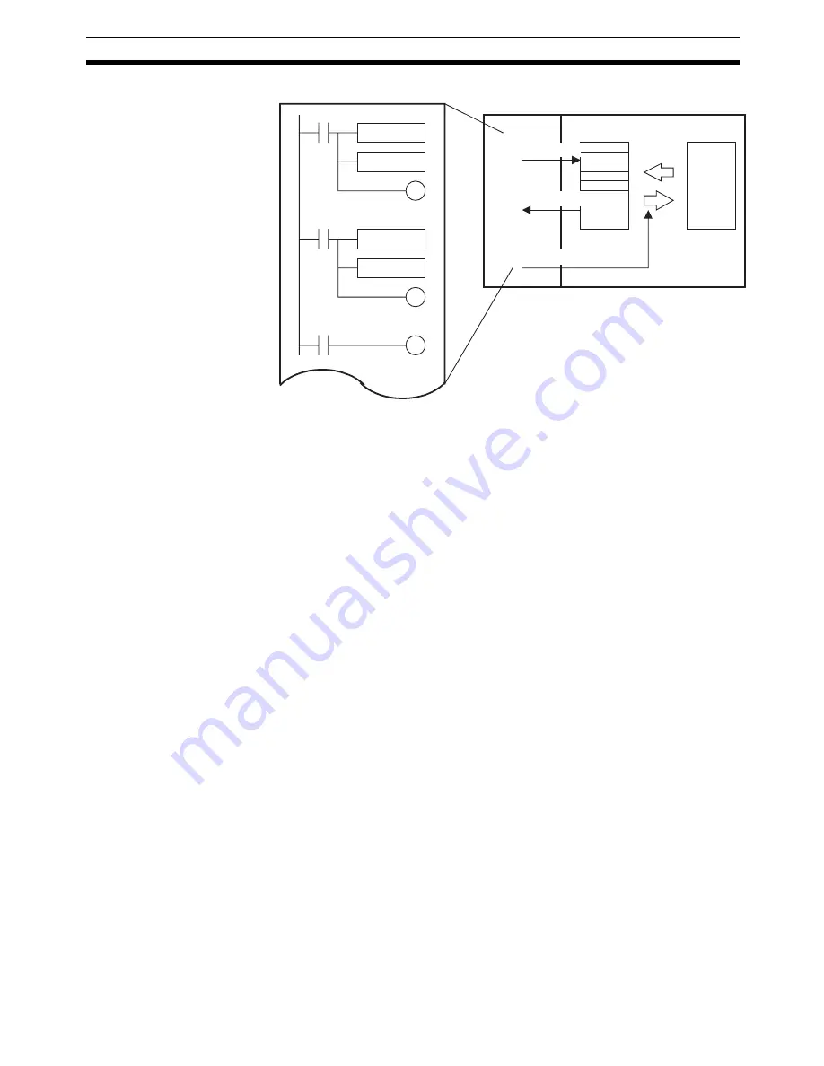
MOV
MOV
MOV
MOV
Ladder program
WRITE DATA
READ DATA
SAVE DATA
CPU Unit
PCU
Writing data
Reading data
Saving data
Internal memory
Powerup
or restart
Flash memory
Summary of Contents for CJ1W-MA - REV 10-2008
Page 3: ...iv ...
Page 5: ...vi ...
Page 21: ...xxii ...
Page 57: ...30 Starting Operation Section 2 2 ...
Page 97: ...70 Wiring Section 3 4 ...
Page 247: ...220 Transferring Servo Parameters Section 5 3 ...
Page 281: ...254 Standard Settings for Servo Drives Using MECHATROLINK Section 6 4 ...
Page 343: ...316 Absolute Encoder Origin Section 8 6 ...
Page 375: ...348 Linear Interpolation Section 9 7 ...
Page 423: ...396 DEVIATION COUNTER RESET Section 10 10 ...
Page 631: ...604 Additional Functions for the CJ1W NCF71 MA Appendix F ...
Page 641: ...614 Index ...
Page 643: ...616 Revision History ...


