


392
Stop Functions
Section 10-9
The status of the Receiving Command Flag, Busy Flag, and Stop Execution
Flag will change if DECELERATION STOP or EMERGENCY STOP is exe-
cuted when an axis operating command is not being executed.
The stop operation will also be performed in the same way as for an active
axis if still in the controlled status while the axis is being stopped (Busy Flag is
ON), such as during direct operation, jogging, when the speed command
value is set to 0 for speed control, or when the axis is being stopped during
torque control.
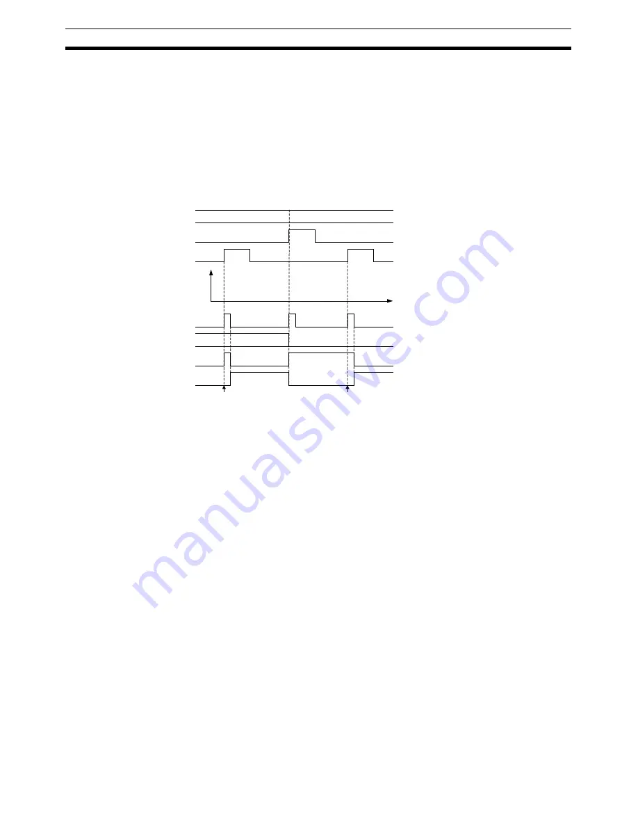
Example: Executing DECELERATION STOP for Speed Control with a Speed
Command Value of 0
0
Speed
If DECELERATION STOP is executed
for an axis that is not being controlled,
while the command is being received,
the Busy Flag will turn ON at least for
one scan and then the Stop Execution
Flag will turn ON.
If DECELERATION STOP is executed
during control (Busy Flag is ON) even
though the axis is stopped, such as speed
control with a speed command value of 0,
the stop operation will be executed and
the status of flags will change.
a = Beginning word of Axis Operating Output Areas specified in Common Para (Axis No.
−
1)
×
25
b = Beginning word of Axis Operating Input Areas specified in Common Para (Axis No.
−
1)
×
25
Time
The Receiving Command Flag turns ON for
at least one cycle time when the movement
command or stop command is received.
Speed command value for
speed control (words a+6, a+7)
SPEED CONTROL
(word a+1, bit 02)
DECELERATION STOP
(word a, bit 15)
Receiving Command Flag
(word b, bit 00)
PCU Positioning Completed
Flag (word b, bit 05)
Busy Flag (word b, bit 13)
Stop Execution Flag
(word b, bit 15)
Summary of Contents for CJ1W-MA - REV 10-2008
Page 3: ...iv ...
Page 5: ...vi ...
Page 21: ...xxii ...
Page 57: ...30 Starting Operation Section 2 2 ...
Page 97: ...70 Wiring Section 3 4 ...
Page 247: ...220 Transferring Servo Parameters Section 5 3 ...
Page 281: ...254 Standard Settings for Servo Drives Using MECHATROLINK Section 6 4 ...
Page 343: ...316 Absolute Encoder Origin Section 8 6 ...
Page 375: ...348 Linear Interpolation Section 9 7 ...
Page 423: ...396 DEVIATION COUNTER RESET Section 10 10 ...
Page 631: ...604 Additional Functions for the CJ1W NCF71 MA Appendix F ...
Page 641: ...614 Index ...
Page 643: ...616 Revision History ...


