


324
Using Direct Operation
Section 9-4
Executing RELATIVE
MOVEMENT
RELATIVE MOVEMENT positions the axis at the specified position using the
position command value in the Axis Operating Output Memory Area as incre-
mental data. RELATIVE MOVEMENT can be executed without the origin
established (No Origin Flag = 1), and the position command value will be
added to the present position (relative travel distance).
The positioning range for RELATIVE MOVEMENT is a command present
position range of
−
2,147,483,648 to 2,147,483,647 (command units) when it
is not limited by limit input signals or software limits. (For details on the com-
mand present position, refer to
7-3 Coordinate System and Present Position
.)
The position command value used as the relative travel distance can be spec-
ified in the range
−
2,147,483,648 to 2,147,483,647 (command units), but if the
positioning is started with a position command value such that the target posi-
tion exceeds the positioning range for RELATIVE MOVEMENT, a Position
Designation Error (axis error code: 3060) will occur, and the positioning oper-
ation will not be executed.
For details on acceleration/deceleration operations during direct operation,
refer to
7-4 Acceleration and Deceleration Operations
.
9-4-2
Direct Operation Timing Charts
Timing Chart for
Movement Command
Execution
The following timing chart is for when RELATIVE MOVEMENT is executed.
The timing chart for ABSOLUTE MOVEMENT is the same, except that posi-
tioning is executed with the absolute position.
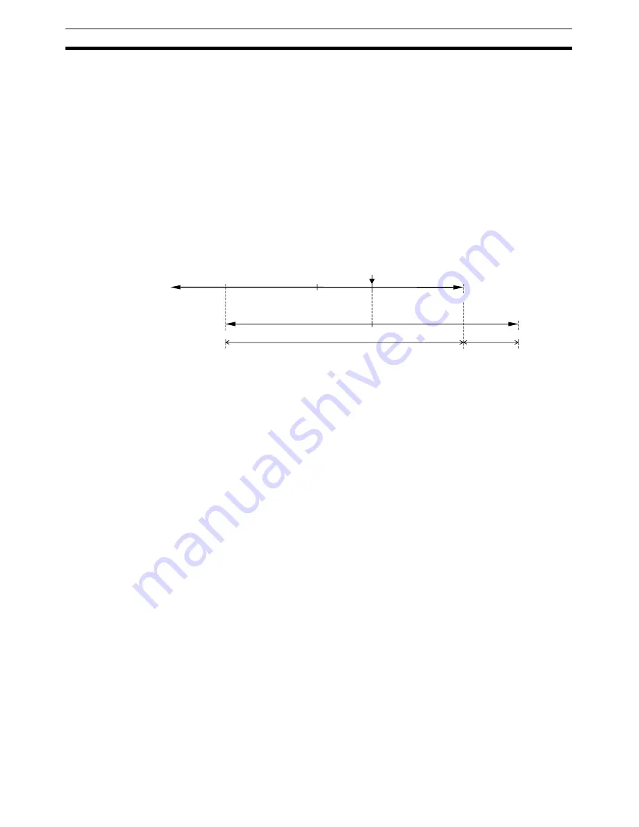
0
0
−
2,147,483,648
2,147,483,647
−
2,147,483,648
2,147,483,647
Command present position
Position command value for
RELATIVE MOVEMENT
Positioning is possible.
RELATIVE MOVEMENT execution
Positioning is not possible
(Position Designation error).
Summary of Contents for CJ1W-MA - REV 10-2008
Page 3: ...iv ...
Page 5: ...vi ...
Page 21: ...xxii ...
Page 57: ...30 Starting Operation Section 2 2 ...
Page 97: ...70 Wiring Section 3 4 ...
Page 247: ...220 Transferring Servo Parameters Section 5 3 ...
Page 281: ...254 Standard Settings for Servo Drives Using MECHATROLINK Section 6 4 ...
Page 343: ...316 Absolute Encoder Origin Section 8 6 ...
Page 375: ...348 Linear Interpolation Section 9 7 ...
Page 423: ...396 DEVIATION COUNTER RESET Section 10 10 ...
Page 631: ...604 Additional Functions for the CJ1W NCF71 MA Appendix F ...
Page 641: ...614 Index ...
Page 643: ...616 Revision History ...


