


318
Direct Operation Overview
Section 9-1
9-1
Direct Operation Overview
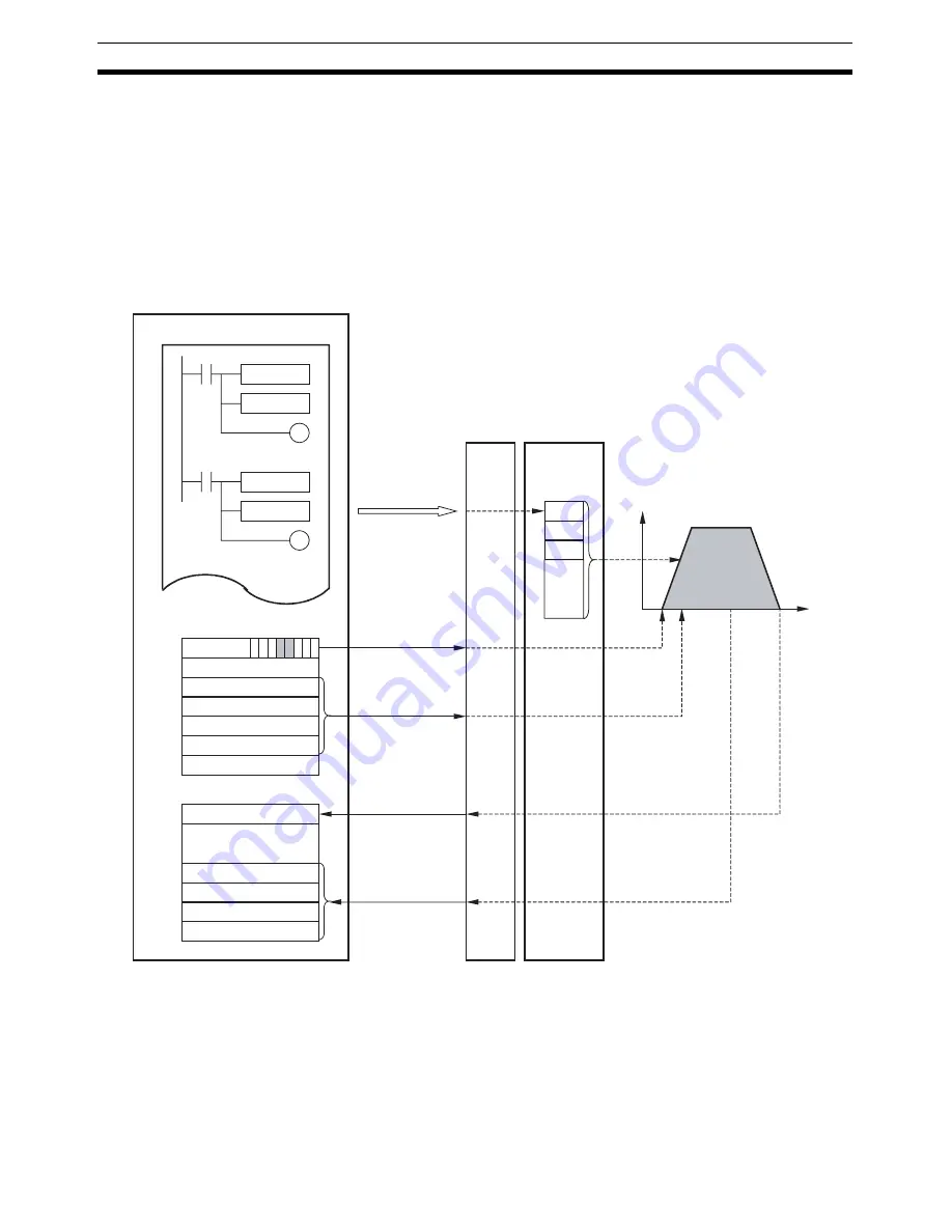
Direct operation of the PCU enables positioning by simply writing target posi-
tion data and target speed data directly from a ladder program to a specified
area in the CPU Unit.
Positioning operations using direct operation are executed according to the
position command value and speed command value in the Axis Operating
Memory Area set in Common Parameters and the acceleration/deceleration
constants set in the Servo Parameters.
The following is an example for a W-series Servo Drive.
The position command value and speed command value set in the Axis Oper-
ating Output Memory Area using the MOV instruction are output to the PCU
automatically during I/O refresh. Direct operation is started when the ABSO-
LUTE MOVEMENT Bit or RELATIVE MOVEMENT Bit allocated in the Axis
Operating Output Memory Area turns ON.
MOV
MOV
MOV
MOV
CPU Unit
a
a+2
a+3
a+4
a+5
b
b+6
b+7
b+8
b+9
Output during I/O refresh
Output during I/O refresh
Input during I/O refresh
Input during I/O refresh
PCU
Pn80A
Pn80B
Pn80C
(1)
(2)
(3)
Ladder program
WRITE SERVO PARAMETER
ABSOLUTE MOVEMENT/
RELATIVE MOVEMENT
Axis Operating Output Memory Areas
Position command value
(rightmost word)
Position command value
(leftmost word)
Speed command value
(rightmost word)
Speed command value
(leftmost word)
Axis Operating Input Memory Areas
Control status
Feedback present position
(rightmost word)
Feedback present position
(leftmost word)
Command present position
(rightmost word)
Command present position
(leftmost word)
a = Beginning word of Axis Operating Output Areas specified in Common Para (Axis No.
−
1)
×
25
b = Beginning word of Axis Operating Input Areas specified in Common Para (Axis No.
−
1)
×
25
ABSOLUTE MOVEMENT
(word a, bit 03)
RELATIVE MOVEMENT
(word a, bit 03)
Execute WRITE SERVO
PARAMETER to
transfer before starting
positioning operations.
Servo Drive
(1) Transfer the Servo Parameters for acceleration/deceleration.
(2) Set the operating data in the Axis Operating Output Data Areas.
(3) Use the bits in the Axis Operating Output Memory Areas to start the positioning operation.
Acceleration/
deceleration
parameters
:
Speed
Time
Summary of Contents for CJ1W-MA - REV 10-2008
Page 3: ...iv ...
Page 5: ...vi ...
Page 21: ...xxii ...
Page 57: ...30 Starting Operation Section 2 2 ...
Page 97: ...70 Wiring Section 3 4 ...
Page 247: ...220 Transferring Servo Parameters Section 5 3 ...
Page 281: ...254 Standard Settings for Servo Drives Using MECHATROLINK Section 6 4 ...
Page 343: ...316 Absolute Encoder Origin Section 8 6 ...
Page 375: ...348 Linear Interpolation Section 9 7 ...
Page 423: ...396 DEVIATION COUNTER RESET Section 10 10 ...
Page 631: ...604 Additional Functions for the CJ1W NCF71 MA Appendix F ...
Page 641: ...614 Index ...
Page 643: ...616 Revision History ...


