


256
PCU Control System
Section 7-1
7-1
PCU Control System
This section describes the configuration, principles, and basic information on
position control when using a control system configured with a PCU and a
W-series Servo Drive.
7-1-1
Control System Configuration and Principles
The control system configured using the PCU basically controls Servomotor
operations using the semi-closed loop method. The semi-closed loop method
detects the number of Servomotor rotations for the command value using the
rotary encoder mounted to the Servomotor, and sends this feedback as the
machine's travel distance. While calculating the deviation between the com-
mand value and actual number of Servomotor rotations, the machine is con-
trolled so that the deviation is compensated to 0.
In the PCU system configuration, a feedback system is configured in the
Servo Drive, without using feedback information for the commands sent from
the CPU Unit's ladder program to the PCU and Servo Drive.
7-1-2
Position Control
The control system configured using the PCU uses the Servo Drive's position
loop to perform position control. The PCU achieves positioning by using the
Servo Drive's position control functions together with control units and coordi-
nate systems.
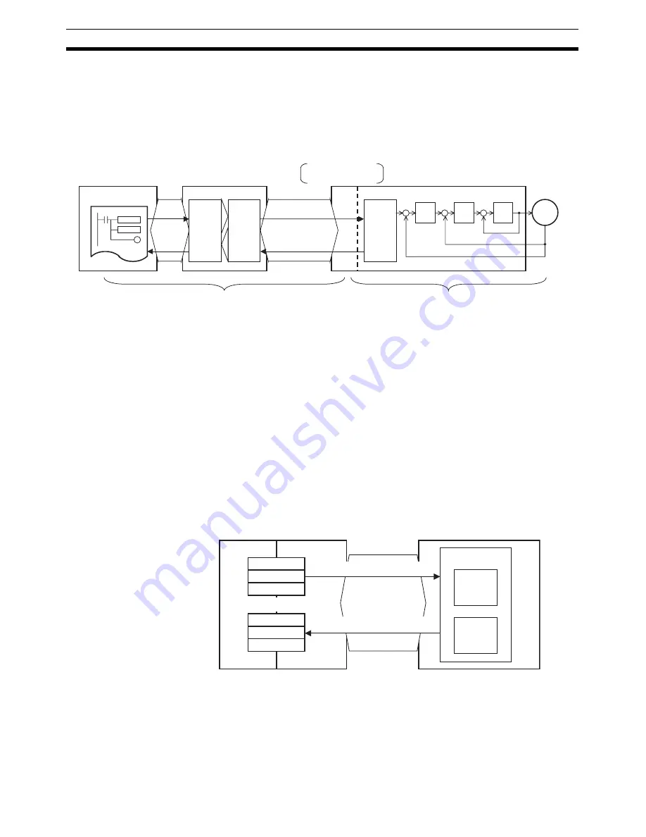
CPU Unit
PCU
Sequence
(ladder program)
Start
I/O words
Status
Com-
mand in-
terpreta-
tion and
process-
ing
Com-
muni-
cations
proc-
essing
Control commands
MECHATROLINK
communications
Status
No feedback system configuration
MECHATROLINK-II
Application Module
Inter-
face
Com-
mand in-
terpreta-
tion and
position-
ing
Servo Drive
Posi-
tion
loop
Speed
loop
Cur-
rent
loop
Servomotor
Feedback system configuration
CPU Unit
PCU
Position command
value
I/O memory area
Present position
Sending command based on the positioning
coordinate system managed by Servo Drive
Monitoring the positioning coordinate
system managed by Servo Drive
MECHATROLINK
communications
Servo Drive
Positioning
Coordinate
calculations
Present
position
Summary of Contents for CJ1W-MA - REV 10-2008
Page 3: ...iv ...
Page 5: ...vi ...
Page 21: ...xxii ...
Page 57: ...30 Starting Operation Section 2 2 ...
Page 97: ...70 Wiring Section 3 4 ...
Page 247: ...220 Transferring Servo Parameters Section 5 3 ...
Page 281: ...254 Standard Settings for Servo Drives Using MECHATROLINK Section 6 4 ...
Page 343: ...316 Absolute Encoder Origin Section 8 6 ...
Page 375: ...348 Linear Interpolation Section 9 7 ...
Page 423: ...396 DEVIATION COUNTER RESET Section 10 10 ...
Page 631: ...604 Additional Functions for the CJ1W NCF71 MA Appendix F ...
Page 641: ...614 Index ...
Page 643: ...616 Revision History ...


