


257
Control Units
Section 7-2
7-2
Control Units
7-2-1
Control Units for Position Control
Control Units for
Position Control
The command units are used as the basic control units for the position com-
mand values and speed command values that the PCU uses in position con-
trol axis operations, such as direct operation, origin searches, and jogging.
(The unit for speeds is command units/s.) These units are determined by the
electronic gear ratio in the Servo Parameters. The Servo Parameter settings
such as
Positioning Completion Range
and
Software Limit
and the present
position monitor unit input in the CPU Unit are also based on these command
units.
The
Electronic Gear Ratio G1/G2
parameters determine the ratio between the
command unit and travel distance (pulse unit) of the Servomotor.
Set the electronic gear ratio such that 0.01
≤
G1/G2
≤
100 when using R88D-
GN
@
G-series Servo Drives, R88D-WT
@
W-series Servo Drives, or SMART-
STEP Junior Servo Drives and such that 0.001
≤
G1/G2
≤
1000 when using
R88D-WN
@
-ML2 W-series Servo Drives.
In the Servo Drive, the control unit is the pulse unit determined by the Servo-
motor's encoder resolution. (The Servo Drive operates internally with a pulse
multiplier of four. Therefore, the Servomotor's encoder resolution multiplied by
four is the number of pulses in one rotation.) The electronic gear ratio is used
to convert the command value (i.e., command units) handled by the PCU into
the control unit (i.e., pulses) used in the Servo Drive (the G1/G2 unit is
pulses/command unit.) When the Servo Drive’s default setting (G1/G2 = 4/1)
is used, the command unit is the number of pulses equivalent to the Servomo-
tor's encoder resolution.
Servomotor with 2,048
(Pulses/Rotation) Encoder
When set to G1/G2 = 8192/1000, the command units for which the Servomo-
tor makes one rotation for a position command value of 1,000 can be
obtained.
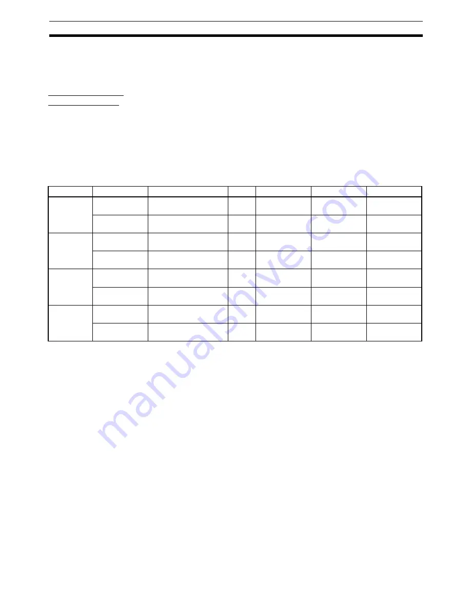
Model
Parameter No.
Parameter name
Unit
Setting range
Parameter size
Default setting
R88D-GN
@
-
ML2
Pn205
Electronic gear ratio 1
(numerator)
---
0 to 131072
4
1
Pn206
Electronic gear ratio 2
(denominator)
---
1 to 65535
4
1
R88D-WT
@
Pn202
Electronic gear ratio G1
(numerator)
---
1 to 65535
2
4
Pn203
Electronic gear ratio G2
(denominator)
---
1 to 65535
2
1
R88D-WN
@
-
ML2
Pn20E
Electronic gear ratio G1
(numerator)
---
1 to
1073741824
4
4
Pn210
Electronic gear ratio G2
(denominator)
---
1 to
1073741824
4
1
SMART-
STEP Junior
Pn20E
Electronic gear ratio G1
(numerator)
---
1 to
1073741824
4
1
Pn210
Electronic gear ratio G2
(denominator)
---
1 to
1073741824
4
1
Summary of Contents for CJ1W-MA - REV 10-2008
Page 3: ...iv ...
Page 5: ...vi ...
Page 21: ...xxii ...
Page 57: ...30 Starting Operation Section 2 2 ...
Page 97: ...70 Wiring Section 3 4 ...
Page 247: ...220 Transferring Servo Parameters Section 5 3 ...
Page 281: ...254 Standard Settings for Servo Drives Using MECHATROLINK Section 6 4 ...
Page 343: ...316 Absolute Encoder Origin Section 8 6 ...
Page 375: ...348 Linear Interpolation Section 9 7 ...
Page 423: ...396 DEVIATION COUNTER RESET Section 10 10 ...
Page 631: ...604 Additional Functions for the CJ1W NCF71 MA Appendix F ...
Page 641: ...614 Index ...
Page 643: ...616 Revision History ...


