


18
Starting Operation
Section 2-2
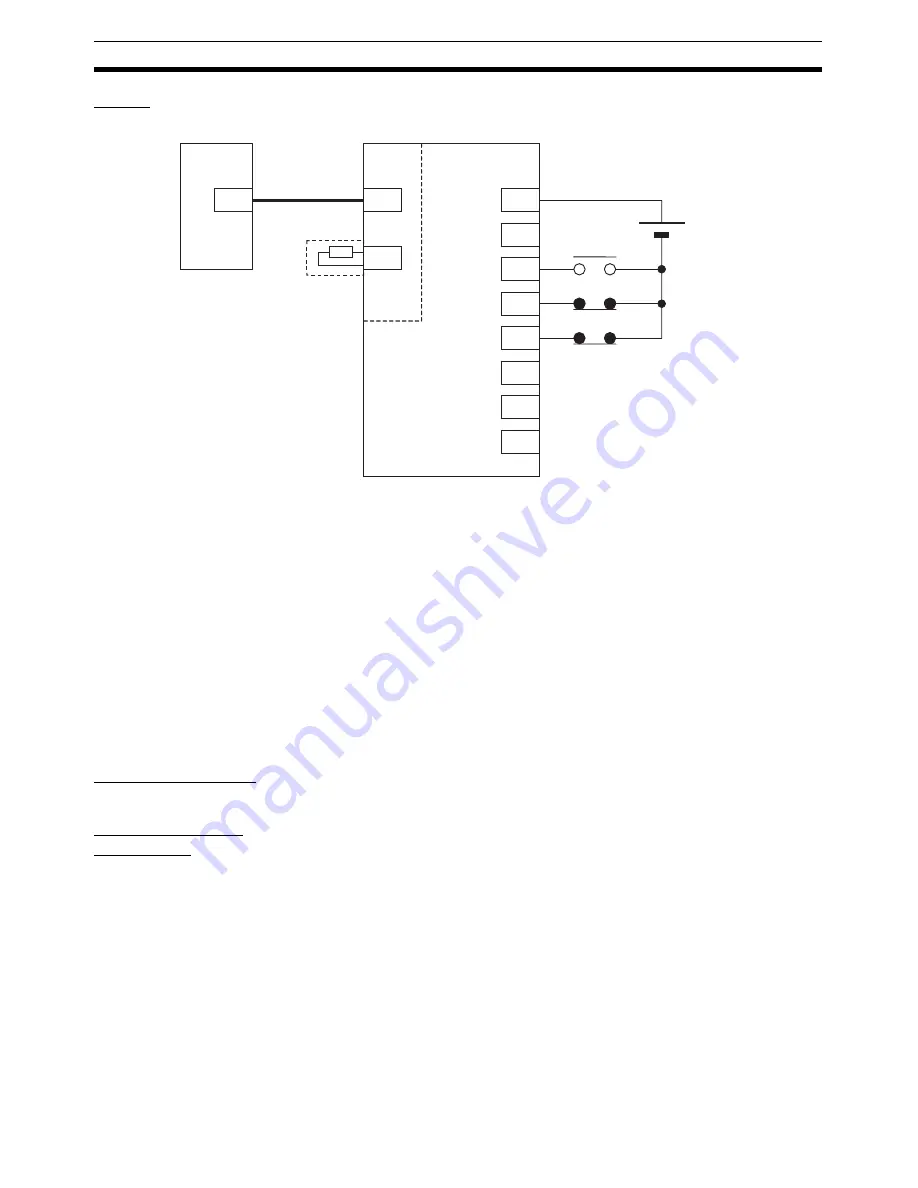
Wiring
Wire the Units as shown in the following diagram.
The Servo Drive's CN1 input signals depend on the input signal allocations,
which are set in this operation example. Of these allocated input signals, the
forward drive prohibit input (forward rotation limit input) and reverse drive pro-
hibit input (reverse rotation limit input) are used as N.C. contacts. Therefore,
connect them so that they are normally ON. The origin proximity signal and
external latch inputs 1 to 3 are not used in this operation example and there-
fore do not need to be wired.
The above diagram shows the wiring for the PCU, Servo Drive, MECHA-
TROLINK-II Application Module, and external control input signals at the
Servo Drive. Refer to each of the CPU Unit and Servo Drive operation manu-
als for details on wiring the CPU Unit and Servo Drive power supply and con-
necting the Servo Drive and Servomotor.
2-2-3
Setting the PCU
Creating I/O Tables
Turn ON the power to the PLC and create the I/O tables. Refer to the
CJ
Series PLC Operation Manual
for details on creating I/O tables.
Setting Common
Parameters
Set the Common Parameters of the PCU. The minimum required Common
Parameters that must be set are as follows:
• Axis Operating Output Memory Area designation
• Axis Operating Input Memory Area designation
• Scan list setting (information registered for axes connected to MECHA-
TROLINK communications)
Common Parameters are transferred to the PCU using the WRITE DATA Bit in
the Common Operating Memory Area. D01000 to D01011 are used for data
to be transferred.
CN6A
CN6B
CN1
+24VIN
(Not used.)
DEC
POT
NOT
EXT1
EXT2
EXT3
47
40
41
42
43
44
45
46
24 V DC
MLK
CJ1W-NCF71
JEPMC-W6003-01
JEPMC-W6022
Terminator
JUSP-NS115
R88D-WT01HL
Origin proximity signal
Forward rotation limit
input
Reverse rotation limit
input
Summary of Contents for CJ1W-MA - REV 10-2008
Page 3: ...iv ...
Page 5: ...vi ...
Page 21: ...xxii ...
Page 57: ...30 Starting Operation Section 2 2 ...
Page 97: ...70 Wiring Section 3 4 ...
Page 247: ...220 Transferring Servo Parameters Section 5 3 ...
Page 281: ...254 Standard Settings for Servo Drives Using MECHATROLINK Section 6 4 ...
Page 343: ...316 Absolute Encoder Origin Section 8 6 ...
Page 375: ...348 Linear Interpolation Section 9 7 ...
Page 423: ...396 DEVIATION COUNTER RESET Section 10 10 ...
Page 631: ...604 Additional Functions for the CJ1W NCF71 MA Appendix F ...
Page 641: ...614 Index ...
Page 643: ...616 Revision History ...


