


340
Linear Interpolation
Section 9-7
Note
When executing linear interpolation operations, the Acceleration Constant
Switching Speed (Pn80C) and the Deceleration Constant Switching Speed
(Pn80F) in the Servo Parameter Area must each be set to 0. Linear interpola-
tion operations cannot be properly executed if any number other than 0 is set.
Linear interpolation operations can be executed for this PCU only with a
1-step acceleration/deceleration curve.
Axis Operating Output
Memory Areas (Operating
Commands)
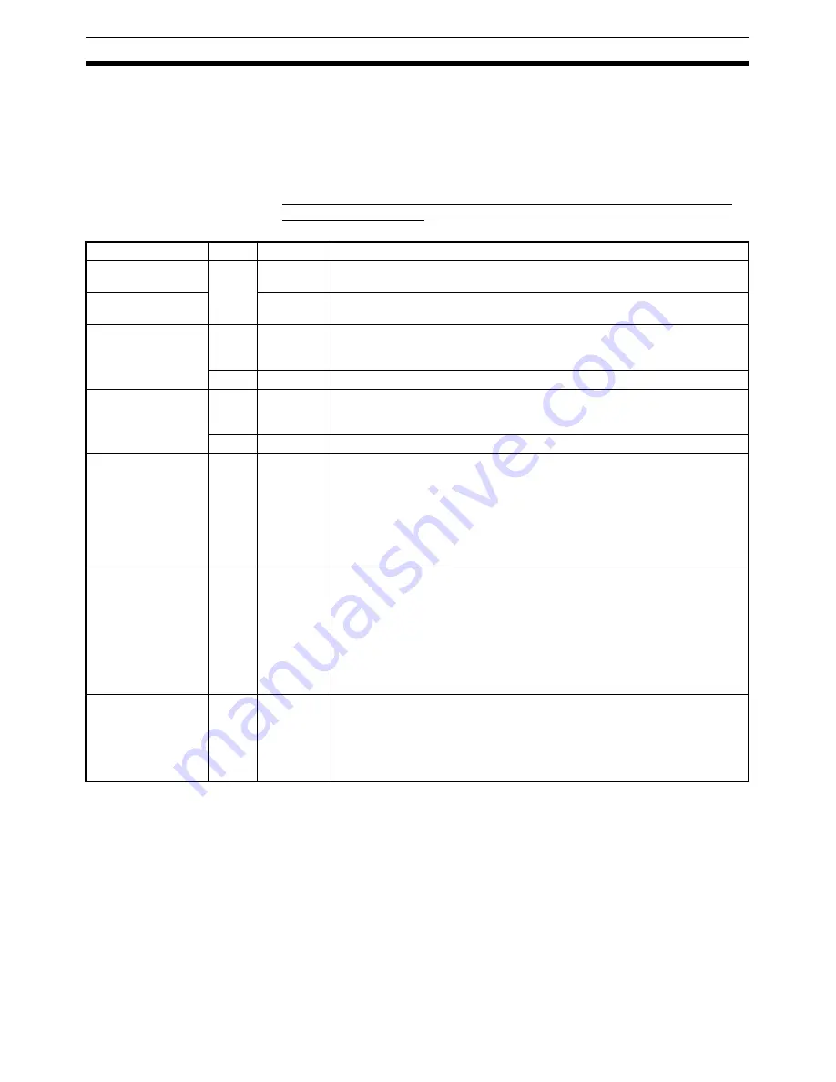
Settings for Linear Interpolation Operations: Axis 1, Axis 5 Operating
Output Memory Areas
a = Beginning word of Axis Operating Output Areas specified in Common
Para (Axis No.
−
1)
×
25
Name
Word
Bits
Contents
LINEAR INTERPO-
LATION SETTING
a
00
0
→
1: Starts linear interpolation setting
1: LINEAR INTERPOLATION START valid.
LINEAR INTERPO-
LATION START
01
0
→
1: Starts linear interpolation movement
(Valid only when LINEAR INTERPOLATION SETTING = 1)
Option Command
Value 1
a+10
---
Linear interpolation acceleration time
Unit: ms
Command range: 0 to 65535 (0000 hex to FFFF hex)
a+11
---
Not used (Set value disabled.)
Option Command
Value 2
a+12
---
Linear interpolation deceleration time
Unit: ms
Command range: 0 to 65535 (0000 hex to FFFF hex)
a+13
---
Not used. (Set value disabled.)
Interpolation Axis
Designation
a+21
00 to 03
(Axis 1 to
Axis 4)
04 to 07
(Axis 5 to
Axis 8)
0: Not designated as interpolation axis.
1: Designated as interpolation axis.
Designates axes for executing linear interpolation.
Combinations of axes 1 to 4 are designated in bits 00 to 03 (Axis 1 Operat-
ing Output Memory Area), and combinations of axes 5 to 8 are designated
in bits 04 to 07 (Axis 5 Operating Output Memory Area).
Bits 00 to 03, and bits 04 to 07, correspond respectively to axes 1 to 4 and
axes 5 to 8.
Interpolation Posi-
tion Designation
a+22
00 to 03
(Axis 1 to
Axis 4)
04 to 07
(Axis 5 to
Axis 8)
0: Execute interpolation operations using absolute position.
1: Execute interpolation operations using relative position.
Specifies, for axes designated by the interpolation axis designation, whether
positioning in interpolation operations is to be executed using absolute or
relative positions.
Positions for axes 1 to 4 are designated in bits 00 to 03 (Axis 1 Operating
Output Memory Area), and positions for axes 5 to 8 are designated in bits
04 to 07 (Axis 5 Operating Output Memory Area). These bits correspond
respectively to axes 1 to 4 and axes 5 to 8.
Interpolation Speed
Command Value
a+23
a+24
---
Speed command value (rightmost word)
Speed command value (leftmost word)
Unit: Command units/s
Command range: 0 to 2,147,483,647 (00000000 hex to 7FFFFFFF hex)
For details on speeds for interpolation operations, refer to
Linear Interpola-
tion Operation Speeds
on page 346.
Summary of Contents for CJ1W-MA - REV 10-2008
Page 3: ...iv ...
Page 5: ...vi ...
Page 21: ...xxii ...
Page 57: ...30 Starting Operation Section 2 2 ...
Page 97: ...70 Wiring Section 3 4 ...
Page 247: ...220 Transferring Servo Parameters Section 5 3 ...
Page 281: ...254 Standard Settings for Servo Drives Using MECHATROLINK Section 6 4 ...
Page 343: ...316 Absolute Encoder Origin Section 8 6 ...
Page 375: ...348 Linear Interpolation Section 9 7 ...
Page 423: ...396 DEVIATION COUNTER RESET Section 10 10 ...
Page 631: ...604 Additional Functions for the CJ1W NCF71 MA Appendix F ...
Page 641: ...614 Index ...
Page 643: ...616 Revision History ...


