


322
PCU Data Settings for Direct Operation
Section 9-3
a = Beginning word of Axis Operating Output Areas specified in Common
Para (Axis No.
−
1)
×
25
The settings of the following are enabled when the movement command start
bit turns ON: Position command value, Acceleration/Deceleration Curve Des-
ignation Bit, Interrupt Feeding Designation Bit, and Forward/Reverse Rotation
Current Limit Designation Bit.
The speed command value can always be changed during operation. By over-
writing the speed command value, the speed for the positioning operation can
be changed.
The G-series Servo Drives do not support exponential curve designation fil-
ters. When using a G-series Servo Drive, do not attempt to use an exponential
curve designation.
The SMARTSTEP Junior Servo Drives do not support acceleration/decelera-
tion filters and torque limits. When using a SMARTSTEP Junior Servo Drive,
do not attempt to use an acceleration/deceleration curve designation or for-
ward/reverse torque limit designation.
Note
Do not set both the exponential curve designation and S-curve designation to
1 (enabled) in the acceleration/deceleration curve designation. Enabling both
settings may cause a malfunction.
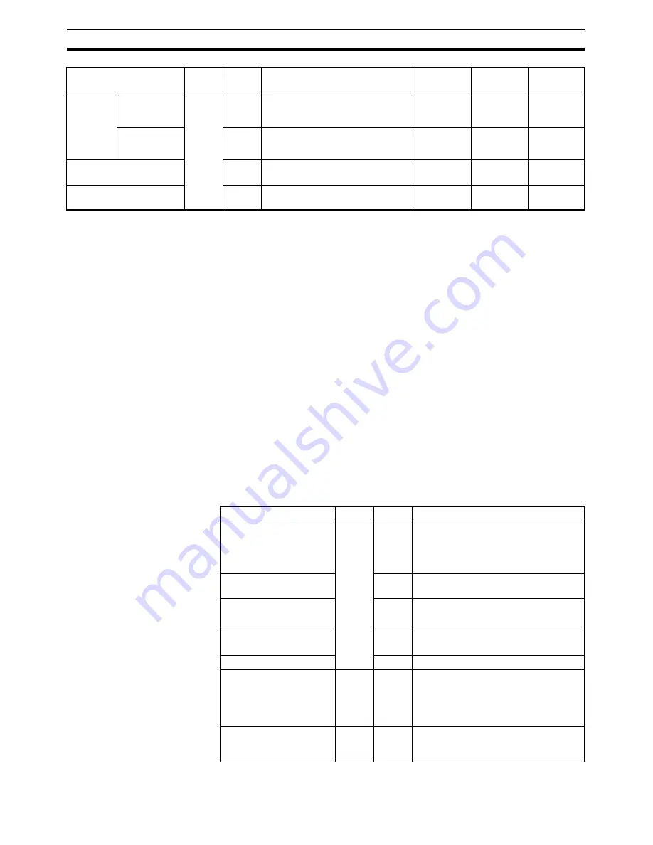
Axis Operating Input Memory Areas (Monitoring)
Accelera-
tion/decel-
eration
curve
designa-
tion
Exponential
curve desig-
nation
a+16
03
1: Use exponential accelera-
tion/deceleration curve.
Not sup-
ported
Supported
Not sup-
ported
S-curve des-
ignation
04
1: Use S-curve acceleration/decel-
eration curve.
Supported
Supported
Not sup-
ported
Forward rotation current
limit
14
1: Use forward torque limit.
Supported
Supported
Not sup-
ported
Reverse rotation current
limit
15
1: Use reverse torque limit.
Supported
Supported
Not sup-
ported
Name
Word
Bits
Contents
G Series
W Series
SMARTST
EP Junior
Name
Word
Bits
Contents
Receiving Command
Flag
b
00
0: Command reception enabled.
0
→
1: Command reception started.
1: Receiving command (command
reception disabled).
PCU Positioning Com-
pleted Flag
05
0
→
1: Positioning is completed.
No Origin Flag
06
0: Origin established.
1: No origin established.
Error Flag
12
0: No axis error.
1: Axis error has occurred.
Busy Flag
13
1: Axis busy (axis operation executing)
Feedback present posi-
tion
b+6
b+7
---
Present position:
Feedback present position (rightmost
word)
Feedback present position (leftmost
word)
Command present posi-
tion
b+8
b+9
---
Present position:
Command position (rightmost word)
Command position (leftmost word)
Summary of Contents for CJ1W-MA - REV 10-2008
Page 3: ...iv ...
Page 5: ...vi ...
Page 21: ...xxii ...
Page 57: ...30 Starting Operation Section 2 2 ...
Page 97: ...70 Wiring Section 3 4 ...
Page 247: ...220 Transferring Servo Parameters Section 5 3 ...
Page 281: ...254 Standard Settings for Servo Drives Using MECHATROLINK Section 6 4 ...
Page 343: ...316 Absolute Encoder Origin Section 8 6 ...
Page 375: ...348 Linear Interpolation Section 9 7 ...
Page 423: ...396 DEVIATION COUNTER RESET Section 10 10 ...
Page 631: ...604 Additional Functions for the CJ1W NCF71 MA Appendix F ...
Page 641: ...614 Index ...
Page 643: ...616 Revision History ...


