


422
Basic Program Examples
Section 11-2
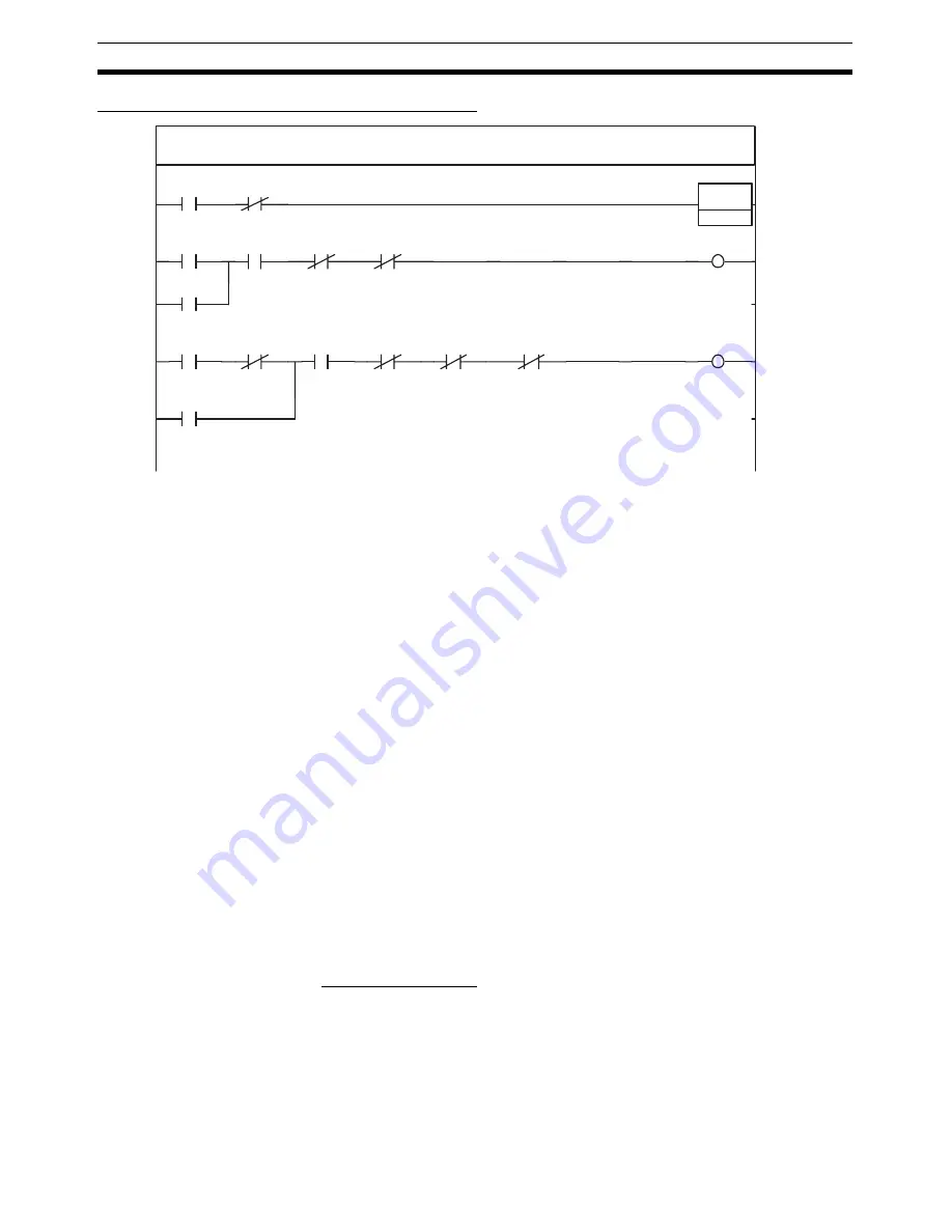
Sample Ladder Program (Emergency Stop)
Note
Deceleration and emergency stops are possible only when the Servo is
locked. If the Servo is unlocked, these stop commands will be ignored. In the
above programming example, the Servo ON Flag is inserted as an output
condition so that DECELERATION STOP, EMERGENCY STOP, and work bits
do not remain ON even if a deceleration stop or emergency stop is executed
when the Servo is not locked.
11-2-10 Jogging
Overview
This sample program performs jogging with the Servo Drive connected via
MECHATROLINK communications. MECHATROLINK communications start
(i.e., a connection is established), and after executing SERVO LOCK, jogging
is executed while the Servomotor is in a servo locked state.
In this programming example, jogging is executed for the Servo Drive regis-
tered at axis 1 when the Jog Bit turns ON in the Axis Operating Output Mem-
ory Area. The Axis Operating Output/Input Memory Areas are based on the
settings of the Common Parameter Area, as shown below. The application
example in
11-3-1 Initial PCU Settings
shows a sample program that can be
used to make the following settings.
Beginning word of Axis Operating Output Memory Area: CIO 0000
(Axis 1 Operating Output Memory Area: CIO 0000 to CIO 0024)
Beginning word of Axis Operating Input Memory Area: CIO 1000
(Axis 1 Operating Input Memory Area: CIO 1000 to CIO 1024)
This sample program uses the following parts of the CPU Unit's I/O memory.
Work Area (WR Area)
W206.00 to W206.01
These Work Area bits are used to create the operation timing for function exe-
cution.
Program name: Emergency Stop
Section name: Emergency Stop
000000
(000000)
1000.12
Axis 1 Error
DIFU
(013)
W205.00
000001
(000003)
1.15
1000.13
Axis 1 Busy
1000.15
1000.12
Axis 1 Error
W205.01
W205.01
000002
(000009)
W205.00
1.01
1522.00
1000.15
1000.12
Axis 1 Error
1.15
1.15
Emergency
Stop execution
condition
Execute Axis 1
Emergency Stop
Axis 1 EMER-
GENCY STOP
Executing Axis 1
Emergency Stop
Axis 1 Stop
Execution
Executing Axis 1
Emergency Stop
Execute Axis 1
Emergency
Stop
Axis 1 EMERGENCY
STOP
Axis 1 SERVO
UNLOCK
Axis 1
Communicating
Axis 1 Stop
Execution
Axis 1
EMERGENCY
STOP
1001.03
Axis 1 Servo
ON Flag
Summary of Contents for CJ1W-MA - REV 10-2008
Page 3: ...iv ...
Page 5: ...vi ...
Page 21: ...xxii ...
Page 57: ...30 Starting Operation Section 2 2 ...
Page 97: ...70 Wiring Section 3 4 ...
Page 247: ...220 Transferring Servo Parameters Section 5 3 ...
Page 281: ...254 Standard Settings for Servo Drives Using MECHATROLINK Section 6 4 ...
Page 343: ...316 Absolute Encoder Origin Section 8 6 ...
Page 375: ...348 Linear Interpolation Section 9 7 ...
Page 423: ...396 DEVIATION COUNTER RESET Section 10 10 ...
Page 631: ...604 Additional Functions for the CJ1W NCF71 MA Appendix F ...
Page 641: ...614 Index ...
Page 643: ...616 Revision History ...


