127
After execution of the SLEEP instruction, and following the clock oscillation settling time, a
transition is made to high-speed (medium-speed) mode via direct transition exception
handling. After the transition, PC break interrupt handling is executed, then the instruction at
the address after the SLEEP instruction is executed (figure 6-2 (C)).
(4) When the SLEEP instruction causes a transition to software standby mode or watch mode:
After execution of the SLEEP instruction, a transition is made to the respective mode, and PC
break interrupt handling is not executed. However, the CMFA or CMFB flag is set (figure 6-2
(D)).
SLEEP instruction
execution
High-speed
(medium-speed)
mode
SLEEP instruction
execution
Subactive
mode
System clock
→
subclock
Direct transition
exception handling
PC break exception
handling
Execution of instruction
after sleep instruction
Subclock
→
system clock,
oscillation settling time
SLEEP instruction
execution
Transition to
respective mode
Direct transition
exception handling
PC break exception
handling
Execution of instruction
after sleep instruction
PC break exception
handling
Execution of instruction
after sleep instruction
(A)
(B)
(C)
(D)
SLEEP instruction
execution
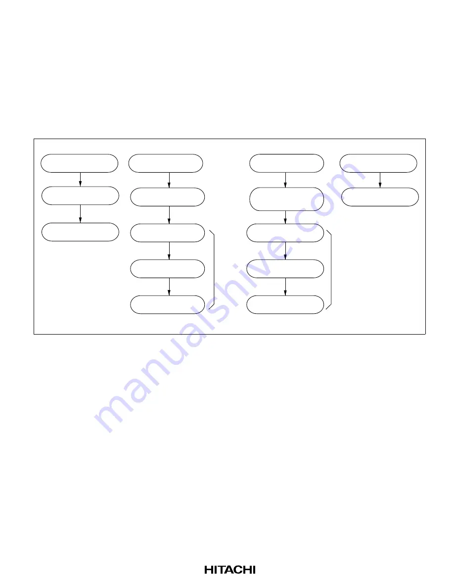
Figure 6-2 Operation in Power-Down Mode Transitions
6.3.5
PC Break Operation in Continuous Data Transfer
If a PC break interrupt is generated when the following operations are being performed, exception
handling is executed on completion of the specified transfer.
(1) When a PC break interrupt is generated at the transfer address of an EEPMOV.B instruction:
PC break exception handling is executed after all data transfers have been completed and the
EEPMOV.B instruction has ended.
(2) When a PC break interrupt is generated at a DTC transfer address:
PC break exception handling is executed after the DTC has completed the specified number of
data transfers, or after data for which the DISEL bit is set to 1 has been transferred.
Содержание H8S/2631
Страница 28: ...xviii Appendix G Package Dimensions 1154 ...
Страница 341: ...316 Transfer SAR or DAR DAR or SAR Block area First block Nth block Figure 9 8 Memory Mapping in Block Transfer Mode ...
Страница 918: ...905 ø DREQ0 DREQ1 tDRQS tDRQH Figure 25 19 DMAC DREQ Input Timing ...
Страница 955: ...943 A 2 Instruction Codes Table A 2 shows the instruction codes ...


