3.2.5
Measuring reference system
3.2.5.1
Function
The correct positioning of the drive requires a defined measuring reference system To define the
measuring reference system, the following steps must be taken during first-time commissioning.
–
Defining the axis zero point
–
Limitation of the usable range by software end positions and/or limit switches
–
Determine the reference point using a homing run and move the factory-set zero point of the
absolute encoder
Signs and directions in the measuring reference system
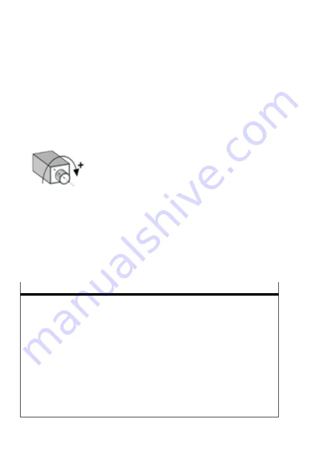
Fig. 34 Positive direction of rotation
The indication of the signs or directions refer to the view on the front side of the motor drive shaft. The
signs of all directional variables are defined at the factory as follows:
–
Positive (+) = direction of movement with clockwise direction of rotation of the motor shaft
–
Negative (–) = direction of movement with anti-clockwise direction of rotation of the motor shaft
The direction of movement of load is, for example, dependent on the spindle type of the axis (clock-
wise/anti-clockwise) and on the gear unit employed. If angular or toothed belt gear units are used, the
opposite assignment of the direction of rotation can be advantageous and parameterised accordingly.
Rotational measuring reference system
Example: rotational drive
Product configuration
120
Festo — CMMT-ST-SW — 2019-02
Содержание CMMT-ST-SW
Страница 615: ......


