


English
32
APPENDIX D
Water Cooled Chillers
1. Design Concept
Water Cooled
Chillers design concept is to release heat via a liquid media (typically water) rather than air of the atmosphere.
The advantage is a more stable operating condition of the refrigeration circuit due to a smaller temperature variation range of
the cooling media alond the year, indipendently from the Ambient Temperature.
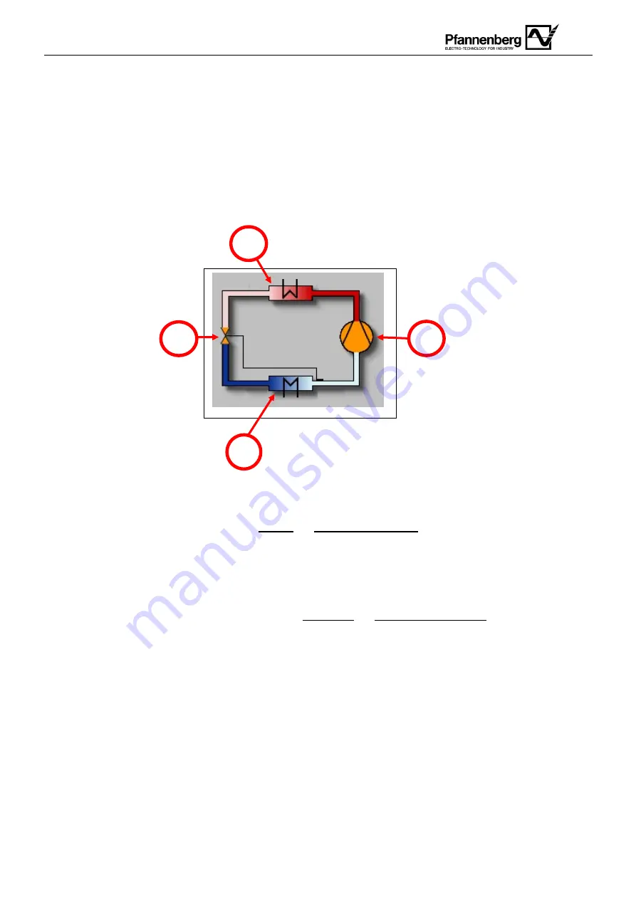
1.1 Functional Diagram
Please Note:
it is of utmost importance to reduce
Fouling
and
Limescale Phenomena
within Condensing Circuit, where Plate
Heat Exchanger and other sensitive equipment may be affected.
Fouling
is the accumulation of unwanted material on solid surfaces to the detriment of function. The fouling material can consist
of either living organisms (bio-fouling) or a non-living substance (inorganic or organic).
The most fundamental and usually preferred method of controlling fouling is to prevent the ingress of the fouling species into the
cooling water circuit.
In industrial installations,
macro fouling
is avoided by way of pre-filtration and cooling water debris filters.
Minimum filtration level required: 90µm
In the case of
micro fouling
, water purification is achieved with extensive methods of water treatment, micro-filtration, membrane
technology (reverse osmosis, electrodeionization) or ion-exchange resins. The generation of the corrosion products in the water
piping systems is often minimized by controlling the pH of the process fluid, control of oxygen dissolved in water, or addition of
corrosion inhibitors.
It is recommended to proceed with a chemical and phisical analysis of the Condensing Water intended to be used and design a
water tretment system accordingly.
1
2
3
4
Picture 3
2
– Functional Diagram
Summary of Contents for EB 130 WT
Page 20: ...English 20 APPENDIX A1...
Page 21: ...English 21 APPENDIX A2...
Page 26: ...English 26 Max pressure valve Thermostatic Valve Evaporator Refrigerant pipes Fan Pump...
Page 54: ...Deutsch 54 ANLAGE A1...
Page 56: ...Deutsch 56 ANLAGE A2...
Page 62: ...Deutsch 62 H chstdruckventil Thermostatisches Ventil Verdampfer K hlmittelrohre L fter Pumpe...
Page 89: ...Italiano 89 ALLEGATO A1...
Page 91: ...Italiano 91 ALLEGATO A2...
Page 124: ...Espa ol 124 ANEXO A1...
Page 126: ...Espa ol 126 ANEXO A2...
Page 159: ...Fran ais 159 ANNEXE A1...
Page 161: ...Fran ais 161 ANNEXE A2...
Page 177: ...177 1 2 3 4 5 6 7 8 8 1 9 10 11 12 A1 A2 B1 B2 C 1 2 D 1 12 2 EN 60204...
Page 178: ...178 30 435 PSI 5 8 85 PSI PWW PS 12...
Page 182: ...182 4 7 3...
Page 183: ...183 3 b PWW 3 4 PWW 9000 12000 1 PWW 18000 24000 3 4 PWW 9000 12000 1 PWW 18000 24000 4...
Page 187: ...187 60 90 m PFANNENBERG 18 15 ISO 4406 10 40 C 45 C 50 C 15 C PFANNENBERG 0 C 11 A1 A2 PWW A2...
Page 189: ...189 11 12 13 14...
Page 190: ...190 l R S T 15 16 17...
Page 191: ...191 5 R S T 18 19 20 21...
Page 192: ...192 PFANNENBERG...
Page 193: ...193 12 KLIXON 2 1 Klixon...
Page 194: ...194 40 C...
Page 195: ...195...
Page 196: ...196 A1...
Page 198: ...198 A2...
Page 200: ...200 B1 n 842 2006 2 PWW 22 23...
Page 201: ...201 A2 20 30 5 7 11 24 25...
Page 202: ...202 24 36 25 309 1 2004...
Page 203: ...203 B2 EB EB150 T EB190 WT...
Page 204: ...204...
Page 205: ...205 C 1 Pfannenberg PFANNENBERG 1 2 3 26 2 1 0...
Page 210: ...210 2 PWW INLET 2 1 31 PWW Air purge valve Max safety valve Refill valve...
Page 211: ...211 D 1 1 1 90 m pH 1 2 3 4 32...