Maintenance 3. Controller Structure
RC180 Rev.17
121
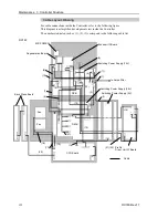
3.2 Diagram of Cable Connections
For the electrical connections of the Controller, refer to the following diagram.
RC180
B
ac
k
pl
ane
O
pt
ion U
ni
t
Option Board
Regenerative
Resistor
Temperature
Sensor
D
P
B
(
D
ri
v
e
P
ow
er
B
oar
d)
Re
ct
ifi
ca
ti
o
n
Ci
rcu
it
, O
v
e
r-
v
o
lt
a
ge
D
et
e
c
ti
on
C
ir
c
ui
t,
Mo
to
r
P
o
w
e
r Co
n
tr
o
l Ci
rc
u
it
,
S
a
fe
ty
Ci
rcu
it
Resistor
T
er
m
inal
B
loc
k
N
oi
s
e F
ilt
er
S
ur
ge
P
rot
ec
tor
C
ir
c
ui
t P
rot
e
c
tor
A
C
200
-2
40V
AC200
-240V
M
ot
or
D
ri
v
er
CP
U
B
o
a
rd
U
SB PC
LA
N
M
em
or
y
T
ri
gger
T
P /
O
P
I / O
5V
PA
R
A
SER
I
Motor Control Circuit
Encoder Receiving Circuit
Motor Power Junction Circuit
1 ax
is
2 ax
is
3 ax
is
FA
N
FA
N
M/C Power
15V
15V
E
nc
oder
S
ignal
7-segment
Encoder I/F Board
(EIB)
EMERGENCY
M/C Signal
Switching
Power
Supply (5V)
A
ddi
ti
onal
A
x
is
I/
F
B
oar
d
(AI
B)
Motor Driver
P
ro
S
ix
D
ri
v
e
r U
n
it
D
M
B
(
D
ri
v
e M
a
in
B
oar
d)
4 ax
is
N
or
m
al
C
on
nec
ti
on
B
oar
d t
o B
o
ar
d
C
o
nn
ec
ti
o
n
C
onn
ec
ti
on U
s
ing
P
ro
S
ix
D
ri
v
e
r U
n
it
C
onn
ec
ti
on U
s
ing
O
pt
io
n U
ni
t
R
ege
ne
rat
ion
M
odul
e C
onn
ec
ti
on
F
or
G
10/
G
20
E
x
ter
nal
I
/F
C
on
ne
c
to
r
Int
e
rn
al
I
/F
C
on
nec
tor
Option Board
M
ot
or
D
ri
v
er
M
ot
or
D
ri
v
er
M
ot
or
D
ri
v
er
Motor Driver
C
ont
rol
S
ignal
Switching
Power
Supply (5V)
Switching
Power
Supply (5V)
E
lec
tr
om
agnet
ic
B
rak
e S
ignal
24V
*1
5 axis
6 axis
AC200
-240V
AC200
-240V
*2
*2
*3
R
egener
at
iv
e
C
ont
rol
B
oar
d
*1
C
onne
c
ti
o
n U
s
ing P
roS
ix
D
ri
v
e
r U
ni
t
*2
R
ec
ti
fi
c
at
ion
C
ir
c
ui
t f
or
M
o
tor
P
ow
er
*3
E
m
er
g
enc
y
S
top D
et
e
c
ti
o
n S
ig
nal
s
uc
h
as
S
af
et
y
D
o
or
D
et
ec
ti
on S
ig
nal
2
4V
R
egener
at
iv
e
R
es
is
tor
C
em
ent
R
es
is
tor
C
em
ent
R
es
is
tor
Summary of Contents for RC180
Page 1: ...Rev 17 EM164C3205F ROBOT CONTROLLER RC180 ...
Page 2: ...ROBOT CONTROLLER RC180 Rev 17 ...
Page 13: ...Safety This section contains information for safety of the Robot System ...
Page 14: ......
Page 20: ......
Page 124: ...Setup Operation 12 Option Units 112 RC180 Rev 17 ...
Page 125: ...Maintenance This section contains maintenance procedures for the Robot Controller ...
Page 126: ...114 ...

