Maintenance 6. Maintenance Parts Replacement Procedures
150
RC180 Rev.17
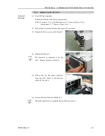
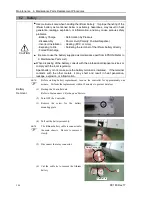
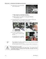
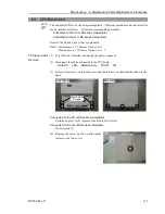
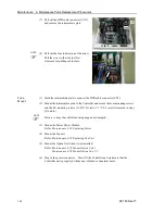
(8) Remove the five screws from the Motor
Driver mounting bracket.
Motor Driver
Mounting
Bracket
Connected to the G10 or G20 series manipulator
Refer to Remove step (9) and remove the connector.
Connected to the G1, G3, G6, RS, C3 or S5 series manipulator
Go on to Remove step (10).
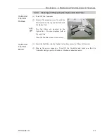
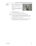
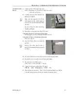
(9) When replacing the first or the second motor driver, compress both ends of the
connector connected to the driver to pull out the connector.
(Remove the connector connected to the replacing motor deriver.)
Connector
2. Pull out
1. Compress
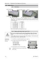
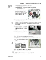
(10) Secure the two thumb head screws
removed in step (3) to the Motor Driver
heat sink.
Pull out the Motor Driver by pulling the
two thumb head screws together evenly.
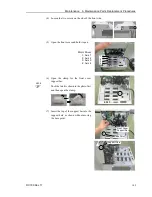
When using the G10 or G20 series manipulator, a cable and a connector are connected
to the first and the second motor driver.
When removing the motor driver, make sure to keep the connector from being stuck.
CAUTION
■
Be careful not to cut your fingers.
The Motor Driver connector may be connected tightly. The connector may be
disconnected suddenly by a strong pull and may cause your fingers to be cut by
the Motor Driver heat sink.
NOTE
Summary of Contents for RC180
Page 1: ...Rev 17 EM164C3205F ROBOT CONTROLLER RC180 ...
Page 2: ...ROBOT CONTROLLER RC180 Rev 17 ...
Page 13: ...Safety This section contains information for safety of the Robot System ...
Page 14: ......
Page 20: ......
Page 124: ...Setup Operation 12 Option Units 112 RC180 Rev 17 ...
Page 125: ...Maintenance This section contains maintenance procedures for the Robot Controller ...
Page 126: ...114 ...


