Maintenance 3. Controller Structure
RC180 Rev.17
119
3. Controller Structure
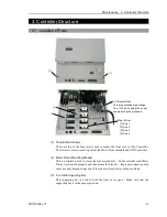
3.1 Location of Parts
(1)
(1)
(2)
(3)
AC Terminal Block
This area contains high voltage.
Turn OFF and unplug the power
supply during the procedure.
[1]
[2]
[3]
[4]
Motor Driver
[1]
:
Axis 1
[2]
:
Axis 2
[3]
:
Axis 3
[4]
:
Axis 4
(1) Thumb Head screws
These are two of the four screws used to mount the front cover of the Controller.
These screws are also used to pull out the Motor Driver module and CPU board unit.
(2) Motor Driver Mounting Bracket
This is a bracket is used to secure the four motor drives. Make sure that each Motor
Driver is connected properly and then mount the bracket. Improper connection may
cause not only improper function of the robot system but also safety problems.
(3) Front Side Supporting Bar
This supporting bar is used to hold the front cover open. Make sure that the
supporting bar is in the proper position.
Summary of Contents for RC180
Page 1: ...Rev 17 EM164C3205F ROBOT CONTROLLER RC180 ...
Page 2: ...ROBOT CONTROLLER RC180 Rev 17 ...
Page 13: ...Safety This section contains information for safety of the Robot System ...
Page 14: ......
Page 20: ......
Page 124: ...Setup Operation 12 Option Units 112 RC180 Rev 17 ...
Page 125: ...Maintenance This section contains maintenance procedures for the Robot Controller ...
Page 126: ...114 ...

