Setup & Operation 2. Part Names and Functions
RC180 Rev.17
15
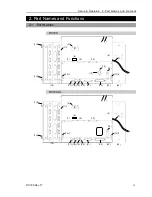
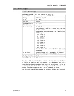
(9) M/C SIGNAL connector
This connector is used for signals such as the Manipulator’s motor encoders, the
origin sensor signals, etc. Connect the Manipulator’s dedicated signal cable.
(10) EMERGENCY connector
This connector is used for input/output from/to Emergency Stop and Safety Door
switches. For details, refer to the
Setup & Operation 9. EMERGENCY
.
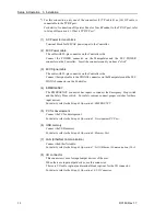
(11) AC IN
The cable for AC 200V power input.
For details, refer to
Setup & Operation 3.3.2 AC Power Cable
.
(12) Thumb Head screw
This is two of the four screws used to attach the front cover of the Controller. Use
these screws to pull out the Motor Driver module and CPU board unit.
-
A spacer is attached to the thumb head screw
on Controllers S/N01001 or later.
Do not remove the spacer.
Installing the front cover using a thumb head screw without a spacer may result in a
cable being stuck and/or malfunction of the Controller.
-
Installing the front cover using other screws may result in cable being stuck and/or
malfunction of the Controller.
(13) POWER switch
Turns ON or OFF the Controller.
* This is not available for RC180-UL. For details, refer to the
Setup & Operation
3.3.2 AC Power Cable
,
For RC180-UL
.
(14) Power Switch metal hasp
To lock the power switch in the OFF position, set the power switch to the OFF
position and mount the metal hasp. Lock the power off for maintenance or repair of
the robot system.
* This is not available for RC180-UL. For details, refer to the
Setup & Operation
3.3.2 AC Power Cable
,
For RC180-UL
.
(15) Cable Clamp
This can be used to secure the M/C Signal Cable and the EMERGENCY cable if
necessary.
(16) Option Unit
Option boards such as expansion I/O board, Fieldbus I/O board, RS-232C board can
be installed. Two slots per unit are available. Up to two units (four slots) are
supported.
For details, refer to
Setup & Operation 12.Option Unit
.
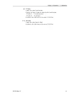
(17) Development PC connection port
This port connects the Controller and the Development PC using a USB cable.
Do not connect other devices except the Development PC.
For details, refer to
Setup & Operation 5. Development PC Connection Port
.
NOTE
Summary of Contents for RC180
Page 1: ...Rev 17 EM164C3205F ROBOT CONTROLLER RC180 ...
Page 2: ...ROBOT CONTROLLER RC180 Rev 17 ...
Page 13: ...Safety This section contains information for safety of the Robot System ...
Page 14: ......
Page 20: ......
Page 124: ...Setup Operation 12 Option Units 112 RC180 Rev 17 ...
Page 125: ...Maintenance This section contains maintenance procedures for the Robot Controller ...
Page 126: ...114 ...

