Setup & Operation 10. I/O Connector
RC180 Rev.17
59
10. I/O Connector
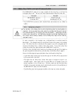
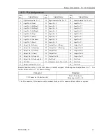
The I/O connector is for connecting your input/output equipment to the system.
Pins
Bit number
Input
24
0 to 23
Output
16
0 to 15
Refer to Setup & Operation 12.2. Expansion I/O board.
For cable wiring, refer to the
Setup & Operation 3.5 Noise Countermeasures
in order to
prevent noise.
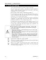
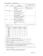
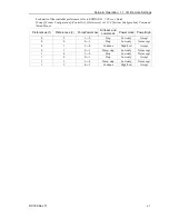
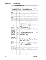
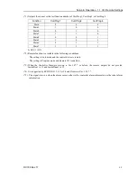
Remote function is initially assigned to both input and output from 0 to 7. For further
details, refer to
11. I/O Remote Settings
.
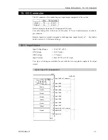
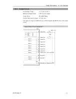
10.1 Input Circuit
Input Voltage Range
: +12 to 24 V
±
10%
ON Voltage
: +10.8 V (min.)
OFF Voltage
: +5 V (max.)
Input Current
: 10 mA (TYP) at +24 V input
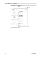
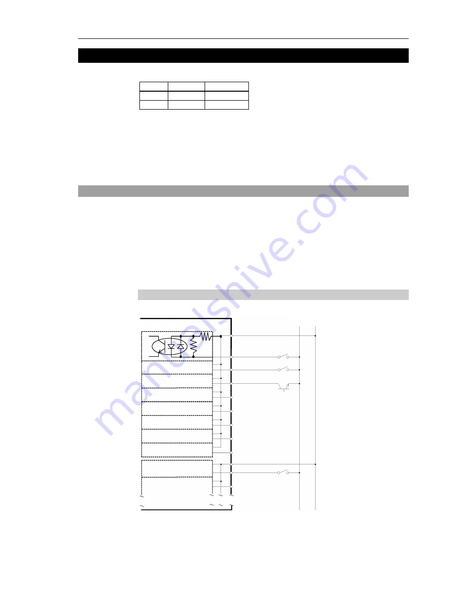
Two types of wiring are available for use with the two-way photo coupler in the input
circuit.
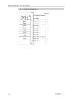
Typical Input Circuit Application 1
1 Input No.0 to 7 common
2 Input No.0
3 Input No.1
4 Input No.2
5 Input No.3
6 Input No.4
7 Input No.5
8 Input No.6
9 Input No.7
I/O-1
(Same)
Omit
GND +DC
18 Input No.8 to 15 common
19 Input No.8
20 Input No.9
(Same)
(Same)
(Same)
(Same)
(Same)
(Same)
(Same)
Summary of Contents for RC180
Page 1: ...Rev 17 EM164C3205F ROBOT CONTROLLER RC180 ...
Page 2: ...ROBOT CONTROLLER RC180 Rev 17 ...
Page 13: ...Safety This section contains information for safety of the Robot System ...
Page 14: ......
Page 20: ......
Page 124: ...Setup Operation 12 Option Units 112 RC180 Rev 17 ...
Page 125: ...Maintenance This section contains maintenance procedures for the Robot Controller ...
Page 126: ...114 ...

