Setup & Operation 12. Option Units
100
RC180 Rev.17
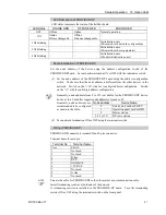
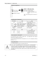
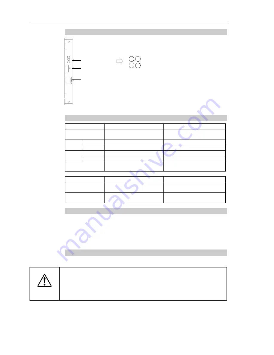
EtherNet/IP Appearance
Status Display LED
Configure Switch
EtherNet/IP Connector
NS
MS
A
CT
L
NK
MS LED : Module status display
NS LED : Network status display
LNK LED : Link status display
ACT LED : Communication packet
reception or transmission status
display
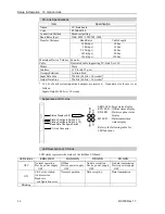
Refer to the following table for functions of
LEDs.
LED Description of EtherNet/IP
LED status
MS
NS
OFF
Power supply OFF
Power supply OFF
or IP address not configured
GRN
ON
Master connected (executing)
Online operating
Blinking
Master connected (idling)
Waiting master connection
RED
ON
Non-recoverable error
Wrong IP address (duplication)
Blinking
Non-recoverable error
Connection time out
GRN/RED
alternate
Self-diagnosing
Self-diagnosing
LED status
LNK
ACT
OFF
No link
No communication packet
reception or transmission
ON
Linking
Communication packet
reception or transmission
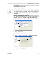
Board Installation of EtherNet/IP
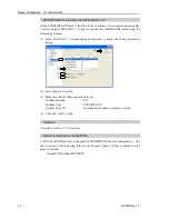
Set all EtherNet/IP board configure switches OFF. If all EtherNet/IP board configure
switches are not OFF, reset error occurs.
All the EtherNet/IP communication configurations are set by the development software
(EPSON RC+ 5.0).
Wiring (EtherNet/IP)
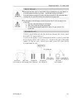
Use a standard Ethernet connector for wiring to the board.
CAUTION
You can use the general Ethernet hub or Ethernet switch for the EtherNet/IP.
However, be sure to a use product complying with the industrial standards or
noise resistant Ethernet cable (STP cable). If you use an office use product or
UTP cable, it may cause communication errors and may not offer the proper
performance.
Summary of Contents for RC180
Page 1: ...Rev 17 EM164C3205F ROBOT CONTROLLER RC180 ...
Page 2: ...ROBOT CONTROLLER RC180 Rev 17 ...
Page 13: ...Safety This section contains information for safety of the Robot System ...
Page 14: ......
Page 20: ......
Page 124: ...Setup Operation 12 Option Units 112 RC180 Rev 17 ...
Page 125: ...Maintenance This section contains maintenance procedures for the Robot Controller ...
Page 126: ...114 ...


