COOPER POWER
SERIES
MN916001EN
Effective October 2018Supersedes October 2016
Energy Automation Solutions
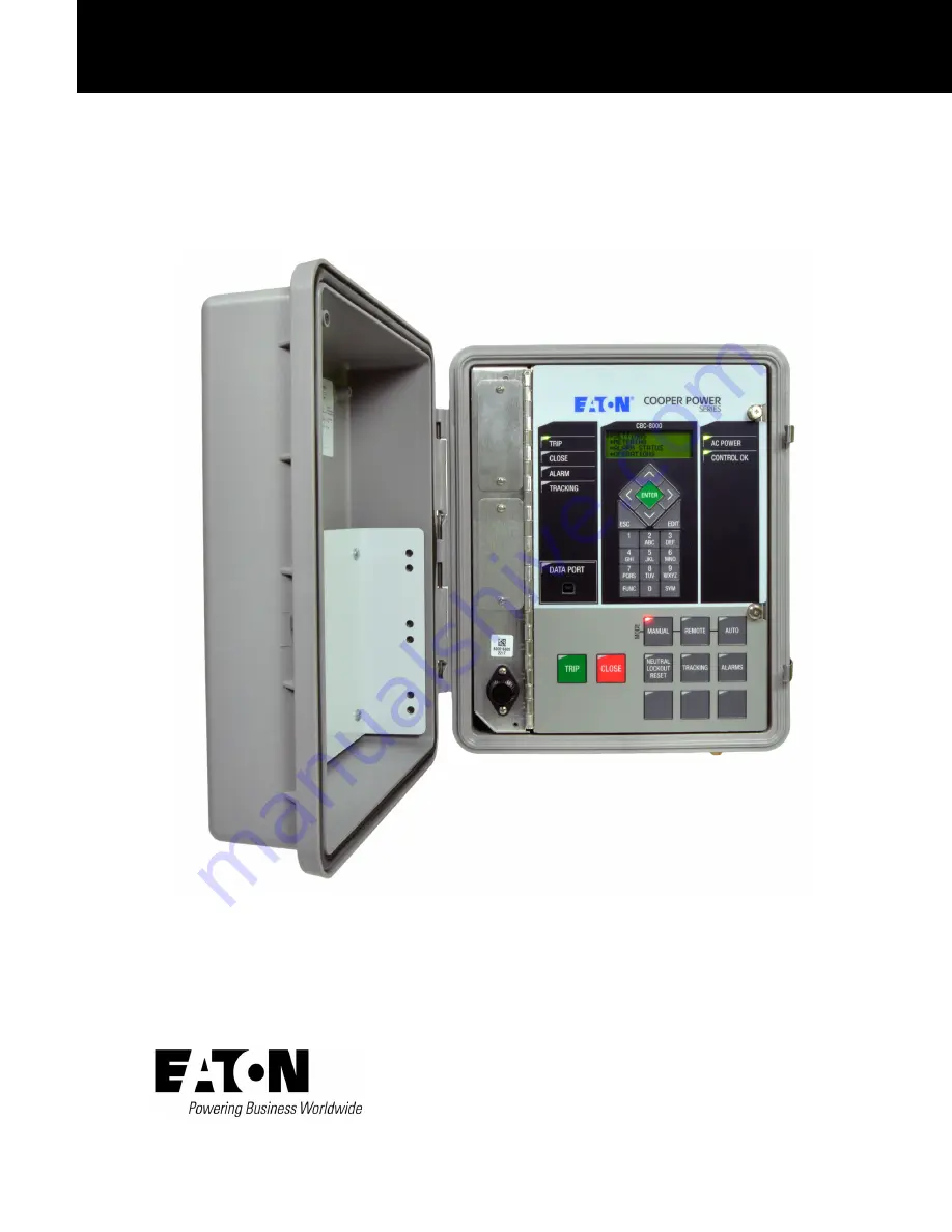
CBC-8000 capacitor bank control installation and operation instructions
Effective October 2018New Information
Page 1: ...ERIES MN916001EN Effective October 2018 Supersedes October 2016 Energy Automation Solutions MN916001EN CBC 8000 capacitor bank control installation and operation instructions Effective October 2018 Ne...
Page 2: ...IFICALLY SET OUT IN ANY EXISTING CONTRACT BETWEEN THE PARTIES ANY SUCH CONTRACT STATES THE ENTIRE OBLIGATION OF EATON THE CONTENTS OF THIS DOCUMENT SHALL NOT BECOME PART OF OR MODIFY ANY CONTRACT BETW...
Page 3: ...ming panel 4 Operating Panel 6 Control features 8 Control security 8 Manual mode 8 Remote mode 8 Automatic mode 9 Alarming 13 Priority table control 13 Metering 14 Data logs 14 Communications 14 Commu...
Page 4: ...service 37 TESTING Testing an installed control 38 Removing the control from service 38 Removing a socket mount control from service 38 Removing a pole mount control from service 39 Removing a panel...
Page 5: ...CBC 8000 capacitor bank control installation and operation instructions MN916001EN October 2018 Eaton com cooperpowerseries iii...
Page 6: ...iv CBC 8000 capacitor bank control installation and operation instructions MN916001EN October 2018 Eaton com cooperpowerseries...
Page 7: ...ertically and the door latch is tightened down to compress the door s neoprene rubber gasket Acceptance and initial inspection Each CBC 8000 control is completely assembled tested and inspected at the...
Page 8: ...ging from 85 to 265 VAC and it operates on both 50 and 60 Hz systems Serial number and date code location The serial number and date of manufacture for the control is printed on a label that is attach...
Page 9: ...tober 2016 will accommodate a 2 AWG pole ground wire Cable security sleeve An optional cable security sleeve is available to securely terminate the cabling that enters the bottom of the enclosure Addi...
Page 10: ...r scroll up to the next available option Change the numerical value from positive to negative or vice versa Change the case of a letter when editing Passwords Figure 5 LCD display and keypad functiona...
Page 11: ...relay control timer is running Bank Operate Time Timers can be viewed by entering Function Code 63 on the front panel or by selecting Display Timers in the ProView NXG software CLOSE The CLOSE LED ill...
Page 12: ...turned off when the capacitor bank operation timer ends Figure 9 TRIP button CLOSE button The CLOSE button shown in Figure 10 allows an operator to manually close the capacitor bank from the front pan...
Page 13: ...me as Auto mode with the addition of regular priority trip and close commands from SCADA and the ProView NXG software Once pressed the REMOTE button places the control in remote mode The REMOTE LED il...
Page 14: ...al mode This is the highest priority command for the CBC and it cannot be overridden by any other command to the CBC Taking the CBC out of Manual mode can only be done through the front panel No comma...
Page 15: ...ontrol is based on the sensor input value and whether or not it is outside of a configurable threshold for a configurable period of time Current control Capacitor bank control is based on the sensor i...
Page 16: ...te Also during the Off time period only manual SCADA fault and emergency controls will be allowed Weekend ON OFF control Weekend On Off control only applies to Saturday and Sunday When the local time...
Page 17: ...ould remain at close above Figure 12 Capacitor banks with 3 phase line voltage current sensors Neutral current fault control Neutral current fault control provides a method to determine if the capacit...
Page 18: ...l operate the working phases into the opposite state to balance the capacitor bank s effect on the line then the control will lock in that state and set an alarm indicating that a neutral current lock...
Page 19: ...ine voltage high low and THD 3 phase kvar high and low kW high and low VAR power factor leading and lagging Temperature high and low Sensor inputs 1 through 6 high and low Neutral current total fundam...
Page 20: ...hange Communication ports The CBC 8000 control has two communication ports The first communication port which is located above the second port supports serial and Ethernet SelectComm communication mod...
Page 21: ...following connectors RJ45 Ethernet connector 13 7 VDC power connector 5 VDC for the SelectComm module provided in the CBC 8000 Wi Fi Retrofit Package P N CBC8K WIFIKIT The power capacity of the radio...
Page 22: ...ion Speed LED Yellow The yellow Link LED indicates the speed of the upstream Ethernet connection An illuminated LED indicates 100Tx and off indicates 10Tx If both the Activity and Speed LEDs are blink...
Page 23: ...s Cooper Power series representative for more information Eaton s Cooper Power series RFN 1200 BlueTree BT 6601 CaIAmp Phantom CaIAmp Viper ELPRO 905U E Freewave Freewave FGR2 PE GE MDS 9810 9710 Tran...
Page 24: ...of a qualified technician or engineer familiar with control functions and programming parameters required for the specific capacitor bank installation The control can be programmed with the Front Pane...
Page 25: ...wer draw on the transformer even though it is only for a brief period of time The CBC 8000 capacitor bank control itself does not consume much power generally it is less than 4 W unless a radio or mod...
Page 26: ...ing by opening the line fuse or disconnect on each phase This provides a visible open indication d Use a shorting stick with an insulated handle to ground all parts of the capacitor bank before touchi...
Page 27: ...l NSLa NSHa Trip Close Option 6 Line Neutral NSHa NSLa Trip Close Option 7 Line Neutral NSHa CSHa Trip Close Option 8 Pole mount with standard male 7 pin DIN connector Option 9 Pole mount with standar...
Page 28: ...The 5 pin DIN signal assignments are as follows Pin Signal A Line B Neutral Common C Close D Trip Open E Not Used An example of the 5 pin DIN male connector with the pin locations is shown in Figure 2...
Page 29: ...from Eaton s Cooper Power series is designed for use with the control s 8 pin DIN connector see Wiring harness options on Page 24 Figure 24 8 pin male DIN connector 14 Pin DIN connector 3 phase meter...
Page 30: ...udes mating connector MS3106F16S 8S The DIN pin assignments and wire colors are associated as follows DIN Pin Wire Color A Black B White C Red D Green E 7 Wire harness The CBC CTRLCBL7P 40 wiring harn...
Page 31: ...r more information about mounting styles see Table 5 on page 21 and the following figures 3 Line up the bottom blades of the control with the socket jaws of the meter socket 4 Gently push the bottom b...
Page 32: ...hen using the front panel the date is entered in MM DD YYYY format and the hour is entered in 24 hour format Refer to the CBC 8000 capacitor bank control ProView NXG application software programming g...
Page 33: ...corresponding 5 pin 7 pin or 14 pin DIN female connector to connect the power and the control cable wires to the control If a retrofit 8 pin DIN male connector is included connect the corresponding se...
Page 34: ...ontrol to a common ground point at the top of the capacitor bank rack A separate or independent grounding wire must run from the capacitor bank rack to the earth following standard industry practices...
Page 35: ...pen c Open the cutouts on the capacitor bank to disconnect the capacitor bank from high voltage power d Wait a minimum of 5 to 10 minutes or whatever time is required by your utility training procedur...
Page 36: ...10 Install a star washer onto each of the four studs for the cable security sleeve 11 Install a wing nut onto each of the four studs for the cable security sleeve and tighten 12 Close the front panel...
Page 37: ...ree different Eaton s Cooper Power series junction boxes For information about wiring line and neutral current sensors to the Eaton s Cooper Power series junction box see Table 7 and Table 8 Equipment...
Page 38: ...000 capacitor bank control installation and operation instructions MN916001EN October 2018 Eaton com Figure 37 CBC 8000 control and Eaton s 3 phase multicore voltage current sensor neutral current sen...
Page 39: ...r bank control installation and operation instructions MN916001EN October 2018 Eaton com 33 Figure 38 CBC 8000 control and Eaton s 3 phase independent voltage current sensor neutral current sensor jun...
Page 40: ...attach the upper blank cover to the front panel as shown in Figure 39 Save the 6 M2 9 sheet metal screws 5 Remove the blank cover 6 Insert the SelectComm module into the opening and gently push the mo...
Page 41: ...to place the control in Manual mode The control should remain in Manual mode while on site This prevents the control from operating on remote commands or local metrics while personnel are near the ca...
Page 42: ...12 The radio modem must be configured to communicate with the control using the setup procedure that was provided by the radio modem manufacturer 13 When the work is completed place the control in Rem...
Page 43: ...ough the ground lug located on the bottom of the control This ground lug is not tied to the neutral side of the control s input power L2 N Please make sure that the ground lug is tied directly to Eart...
Page 44: ...he capacitor bank 9 Verify that the capacitor bank is closed 10 If the capacitor bank closed correctly press the TRIP button to trip the capacitor bank 11 Verify that the capacitor bank is tripped ope...
Page 45: ...the control off of the upper lag bolt and remove from the pole 10 If the control is not to be replaced with another control disconnect the power to the control cables 11 Carefully transport the contro...
Page 46: ...sensor wiring harness and 8 pin DIN connector This assembly is connected to the control with the 8 pin DIN connector that is described in 8 Pin DIN connector sensor inputs only on Page 23 The CBC NCSE...
Page 47: ...lacement kits for the control are available through the factory Service Department To order these kits refer to the Replacement Parts price list for catalog numbers and pricing Contact your local Eato...
Page 48: ...Additional information 42 CBC 8000 capacitor bank control installation and operation instructions MN916001EN October 2018 Eaton com...
Page 49: ......
Page 50: ...information visit Eaton com cooperpowerseries Eaton 1000 Eaton Boulevard Cleveland OH 44122 United States Eaton com Electrical Automation Solutions Division 3033 Campus Drive Suite 350N Minneapolis MN...