


CBC-8000 capacitor bank control description
CBC-8000 capacitor bank control installation and operation instructions
MN916001EN—October 2018
Eaton.com
11
•
Close below
– Perform a close operation when the sensor
input value is below the threshold.
•
Close above trip below
– Perform a close operation when
the sensor input value is above the threshold and perform
a trip operation when the sensor input value is below the
threshold.
Note:
Make sure the actions that are specified for the
minimum and maximum thresholds do not cause
conflicting control operations. For example, the
minimum action cannot be trip above if the maximum
action is close below.
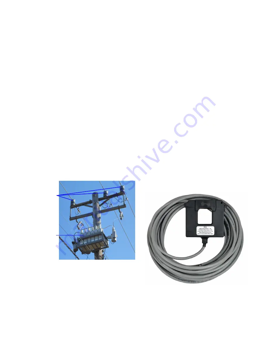
Current control – use case for sensor input control
Current control can be accomplished using the sensor input
controls if the site is equipped with current monitoring
sensors. Figure 12 is a picture of combination voltage and
current sensors installed on all three phases.
As an example, a customer would like to have the capacitor
bank close in above 200 A and open up below 100 A. The
minimum threshold action would be trip below with a value
of 100 and the maximum threshold action would be close
above with a value of 200.
If it is desirable that the capacitor bank remain closed in
between 100 A and 200 A, the minimum threshold action
would be set to close above trip below and the maximum
threshold action would remain at close above.
Figure 12. Capacitor banks with 3-phase line voltage/
current sensors.
Neutral current fault control
Neutral current fault control provides a method to determine
if the capacitor bank is in a fault condition, such as a phase
imbalance. If neutral fault current control is enabled and the
measured
fundamental
neutral current exceeds the
configurable set point for a configurable period of time, the
following occurs:
• The control places the capacitor bank into the opposite
state from the one that caused the fault current.
• All control operations, except for manual control and
SCADA override control, are prohibited.
• The keypad can still be used to view control settings and
data during a fault condition.
• The measured fundamental neutral current, at the time of
the fault, is stored in non-volatile memory. The neutral
current value that caused the fault can then be retrieved at
a later time.
• The LED on the NEUTRAL LOCKOUT RESET button will be
illuminated.
Note:
A neutral current sensor must be connected to the
control prior to enabling neutral current fault control.
The neutral current lockout can be cleared by pressing the
Neutral Lockout Reset
button on the operating panel or by
sending a neutral lockout reset command to the control over
local/remote comms. When the neutral current lockout is
cleared, the fault current value in non-volatile memory is also
cleared and the LED on the NEUTRAL LOCKOUT RESET
button will no longer be illuminated.
Figure 13. Neutral current sensor.
3-Phase Line
Voltage/
Current
Sensors
Capacitor
Banks
Summary of Contents for COOPER POWER SERIES
Page 49: ......


