Maintenance 6. Maintenance Parts Replacement Procedures
160
RC180 Rev.17
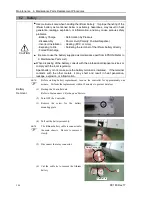
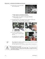
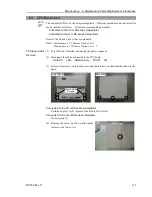
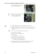
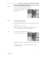
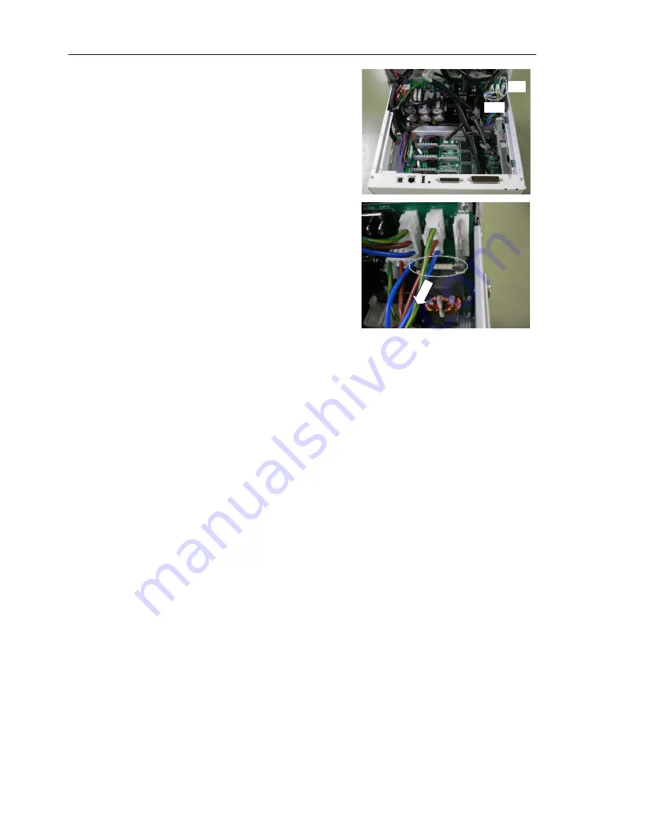
(7) Pull out the DPB cable connector (CN1)
and remove the intermediate plate.
CN1
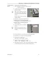
Fuse
(8) Pull out the fuse in direction of the arrow.
Pull the wires to the side to allow
clearance for pulling out the fuse.
Fuse
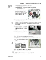
Mount
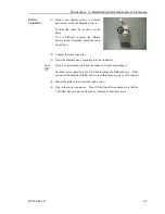
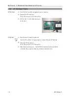
(1) Hold the intermediate plate to connect the DPB cable connector (CN1).
(2) Mount the intermediate plate to the Controller and secure the four mounting screws
and the FG mounting screws (G / RS: 2 screws, C3 / S5: 3 screws) removed in steps
(5) and (6).
Be sure to keep the cable from being trapped or damaged.
(3) Mount the Motor Driver Module.
Refer :
Maintenance 6.3.2 Replacing Motor
(4) Mount the fan unit.
Refer :
Maintenance 6.1.2 Replacing Fan Unit
(5) Mount the Option Unit when it was installed.
Refer :
Maintenance 6.7.2 Mount Option Unit 1
Maintenance 6.7.6 Mount Option Unit 1, 2
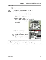
(6) Plug in the power connector. Turn ON the Controller and make sure that the
Controller starts properly without any vibration or abnormal noise.
NOTE
NOTE
Summary of Contents for RC180
Page 1: ...Rev 17 EM164C3205F ROBOT CONTROLLER RC180 ...
Page 2: ...ROBOT CONTROLLER RC180 Rev 17 ...
Page 13: ...Safety This section contains information for safety of the Robot System ...
Page 14: ......
Page 20: ......
Page 124: ...Setup Operation 12 Option Units 112 RC180 Rev 17 ...
Page 125: ...Maintenance This section contains maintenance procedures for the Robot Controller ...
Page 126: ...114 ...

